

05/01/09
Hi, I discovered this site about a week ago and since then I have decided I have to build a robot. I have been experimenting with PIC microcontrollers over the last couple of months anyway so I decided building a robot would be a good opportunity to implement some of the skills I have learnt. I have no previous robot building experience (with the exception of building 'Cybot' from 'Real Robots' magazine. To be honest I didn't know what I was doing, I just followed the instructions.)
***INTRODUCTION***
Once I'd decided I wanted to build a robot I wanted to get my hands on the parts straight away. I had a look at the start here robot and worked out to build it it was going to cost me quite a bit of money. A bit more than I wanted to be spending at the moment and long waits for shipping. For this reason I decided I was going to scavenge parts. The handheld 'dust-buster' broke so I scavenged a motor out of there and I thought I was sorted. I soon found that that motor had a stall current of over 60A. Very quickly I realised this motor was clearly not suitable and would require a very high powered motor driver. I rethought the whole situation and read around here and decided to go for a L293D based motor controller to power two 'Solarbotics' motors with a stall of 600mA each. This was when I worked out there was a better way to go for cost and speed of access to materials. I decided I was going to get the cheapest RC car I could...
***FIRST STAGE***
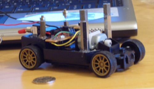
I went down to the local retail park and picked up a small RC motor for about £5 hoping to at least get a small servo out of it. First thing was to check it worked it did so now I was going to pull it apart. Took the cover off and found there was no servo (initial disappointment!) then I realised that it had two small DC motors; one driving the back wheels and one for steering the front. The first step for me was to get a look at the PCB. The PCB was made entirely of discrete components with the exception of one of the black 'blob' looking processor things in the middle. After a long look at the PCB I highlighted where abouts the receiver was and where the motor drivers were (It's a H-bridge style circuit I believe). I carefully chopped straight through the middle of the processor (was the best route I thought. ;)) I then replaced a couple of resistors and drilled a few holes for wires that were needed (power and ground etc hat were on other half of board).
After that carry on I attached a socket to the four pins that were attached to the processor and to my amazement the thing worked despite being slaughtered by my wire cutters. There are four pins when taken high each functions as below...
1. Forward
2. Backward
3. Wheels left
4. Wheels right
If wheels are driven bough forward and back at once etc. bad stuff happens (3A or so flows). The motor driving the wheels has a stall of about 1.5A at 4.5V driving the motor driver and the motor steering the wheels stalls constantly which is how it operates and it stalls at around 600mA.
At this point I could really start to see how the PIC is going to control the robot. I screwed the bit of PCB remaining down and used a small 'blob' of hot glue to hold it firm. I also added four PCB standoffs to attach a second tier to (attached with hot glue gun too). I then wasn't sure what to use as a light but rigid second tier floor. I eventually settled on using the packaging from my PICkit2 from Microchip. I cut a rectangle out, rounded the edges off, drilled the holes and bolted it to the standoffs (I can attach another floor to the standoffs when I need too). I next added a switch to turn the motors on and off located at the back of the robot attached with hot glue. The leads protruding at the moment are for the battery. There is a compartment for 3xAAA but at the moment I'm using a power pack while it's on the desk on it's back. I've got to get a power board sorted yet.
Things I'm adding next...
Led indicator to signal that motors are turned on.
***FUTURE IDEAS***
Need to add a small board probably on second tier maybe with two small relays to select whether the PWM output of the PIC is on the forward pin or the reverse and on the right or left for steering. This stops bad things happening when both forward and backward or left and right are selected at once! This will also allow me to use the PIC16F628 initially which is useful because I'm familiar with it.
Power distribution board probably on the second tier too (second tiers looking full already ;)). I'm not regulating the voltage I don't think and just going to feed everything from the 3xAAA for now and see how it goes. Might get away with it. Can handle the power but don't know about PIC getting an unregulated voltage but we'll see. I think I'll see about regulating it to between 3 and 4 somehow for the PIC.
In the more distant future I hope to add a sensor to the front (for now) but I'm not sure which yet. May go sharp IR but may go the ultrasonic transceiver. I'm thinking I'll mount it on a small servo. Still thinking yet though. Need some headlights (obviously =P). I'll have the PIC and sensor power etc. switched separately to the motor power ie. I'll add another switch.
Well I think that's about it for now... Sorry about the poor pictures (I'm not good with a camera!). Any questions, advice or feedback then please fire away. This seems a very cool place by the way! =]]
-----------------------------------------------------------------------------------------------------------------------------------------
05/01/09
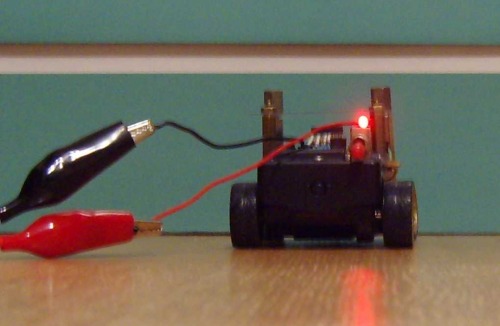
I added the LED to the top of the switch which indicates when the motors are powered up. It is really only viewable when viewed straight-on. That works out pretty well so that it's discrete and not too out of place.
-----------------------------------------------------------------------------------------------------------------------------------------
07/01/09
I've drawn up a schematic for the board that is going after the microcontroller but before the motor driver board. It will be there to select whether the PWM signal is going into driving the wheels forward or backwards and select whether the wheels are going left or right. It will ensure there is never a 'shoot through' situation where the wheels try to go forward and back ward or left and right at the same time. The PCB has two of the pictured schematic on.
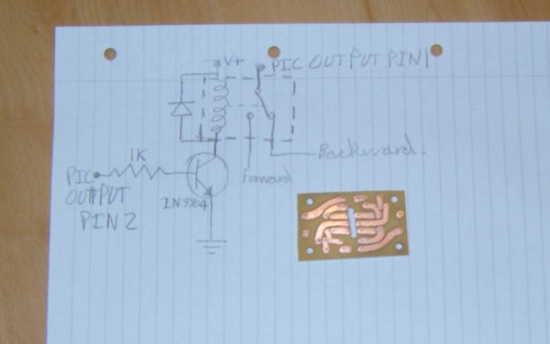
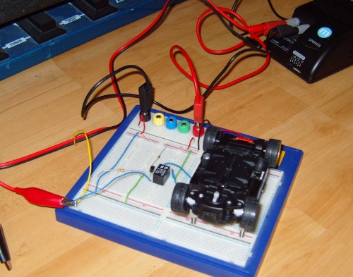
The next update I'll make here will be when I have populated the PCB and have the motors being driven by a PWM test program on my proto board. Then once the board is confirmed to be working and all seems to be going as planned the board will then be mounted on robot and work on the power board commenced.
This is a companion discussion topic for the original entry at https://community.robotshop.com/robots/show/lynx

