UPDATE 15/09/2015:
Here's a new video of Lobsang following a line. It's still (as with everything!) in development stage, but you can see it's pretty fast and can perform tight turns with reasonable accuracy. I use PWM to speed up / slow down the motors, so there is a slight lag between the Duino being commanded to stop a motor and the motor actually stopping, which is giving me a bit of trouble for line following, but I'm sure I can still speed things up. The robot is not driving at top speed (approximately half speed) so I could theoretically go faster but I don't think I can follow lines at top speed.
UPDATE 15/08/2015:
My blog about Lobsang for PiWars has moved to my blog area on LMR. This will be for the other side of Lobsang- my personal robot, not the PiWars competitor (they are one and the same but running different code, sometimes with different modular parts fitted). It will also stop this page being 'bumped up' the current robots list, which I got into a little bit of trouble about previously on a different account.
UPDATE 14/08/2015:
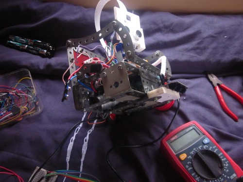
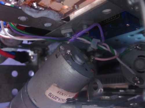
Disaster! Somehow, the wire for the right motor has snapped! It's in a place where there is no movement, yet it has snapped! I need to solder it up quick as I have some line following code I want to test out. Right now only the left motor works so it can't follow lines. Here are some pictures to illustrate: (yes, that's my bed. It's my favourite workbench, even though I have an official work surface!)
MICRO-UPDATE 12/08/2015:
The wonderful people at PiWars / CamJam have selected me to compete! I'm Blaenrhyd Innovation and you can see the proof here. I'm very pleased to be a part of something so big and fun. I'm going to start blogging about my build process more now, and hopefully earn some points! :)
ORIGINAL POST:
If you are familiar with the combined work of the late Terry Pratchett and Stephen Baxter, then you will understand why I have called this robot Lobsang. If not, I shall explain - in their book "The Long Earth" a load of code appears on a super computer. It claims to be the reincarnation of a tibetan car mechanic, called Lobsang. There is no proof that the mechanic was reincarnated, but the artificial intelligence remembers the tibetan's life and is certainly very convincing at being a human (in a machine at least).
This robot looks up to the fictional Lobsang with great respect, acknowledging it's own great inferiority. Or at least, it will soon, when the Raspberry Pi has some code on it to make it say things like "Oh Lobsang, truly are you a great being. I bow down before you." or perhaps even "Obstacle detected 34.71 centimetres away, 12 degrees to the left! I will turn 76 degrees to the right in 2.69 seconds, using 0.73 Joules of power.".
Anyway introduction aside, I will get down into the nitty gritty nerdy geeky of it all. I'm using a Raspberry Pi from Pimoroni with a Coupe Royale (aka purple case) for the processor, I have a cheap L298N dual motor controller to handle the higher motor voltage/current, everything runs off eight AA batteries that give 9.6V so 7.5V approximately to the motors (the L298N creates a ~2V drop) and then of course 5V to the Raspberry Pi, through a 5V convertor that I made up at Aberystwyth Robotics Club (thanks Steve!)
There is a simple sensor cluster mounted on the two central servos (intentionally NOT arranged in a cute ultrasonic eyes way). The body is finished, the wiring is pretty much there, and most of the sensors are fitted and connected. I had some trouble with the power supply for the Raspberry Pi, the voltage at the 5V regulator end was 5V, but at the other end of the wires it dropped to around 1V. This was because the Raspberry Pi draws ~250mA current and the wires were very thin (just standard male to female jumpers). You will see in the pictures that the power supply wires are noticably thicker. I swapped the thin ones for some old caravan wiring I'd removed and now the Pi powers beautifully. I'm just hoping that the voltage drop when the motors begin turning isn't too much to reset the Pi. I'm using a RasPiO Duino for 2x PWM for the motor enables so the stopping and starting of the motors is more gradual and doesn't interfere with the Pi's power, servo control for the sensor cluster, and a layer of I/O protection in case anything goes wrong- the ATMega gets fried not the Pi. Currently nothing connects to the Pi - it does all the computing then passes commands to the Duino via serial and then the Duino reads them and acts on them (eg. "MR32" sets the Right Motor at forward 16 (32 - 16 = 16) or "MB12" sets Both Motors to backward 4 (12 - 16 = -4) only this value is then scaled up to 0-255 for pwm speeds)
There is a 170 point breadboard beside the battery to hold the battery in place properly, and for any quick tests or wiring that may need doing.
A lot of soldering has been done for this project (something of a novelty to me) as many of the connections had to be custom designed. The 9V battery clip had very thin wires on it (though I suppose 20 for 60p from china was still a pretty good deal) so I removed them and soldered some nice thick ones on, and I had to swap the wires on the 5V regulator too. The power connector at the Raspberry Pi end had to combine the thick caravan wires with the small delicate GPIO header pins. I cobbled a JST style connector from two of the female headers on an (old dead) Arduino board and to my pleased surprise it worked first time (You know how it is, nothing electronic EVER works first time! Powerpoint presentation or little home made project). There is something about that confident glow of a power on LED - without the panic causing acrid smoke - that warms a little geek's heart...
Here are some pictures to better illustrate my explanation...
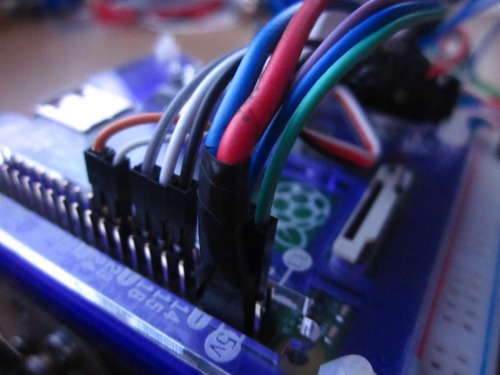
The Raspberry Pi with all the connectors in. The two thicker ones are Pi power. I'm powering the Pi from the 5V on the GPIO, not the micro USB socket. I'll probably have to rearrange the connections when the little OLED screen arrives so I can communicate with it. You can see the power connector is wrapped in electrical tape- this robot is held together 50% bolts and 50% blue tack, velcro and tape!
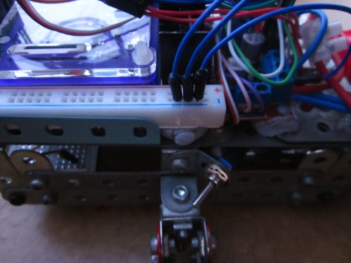
The power rail behind the Raspberry Pi, the L298N tucked under that jumble of wires on the right (I wish they made everything wireless!) and the power switch down by the tail. I put it there because I figured it's very protected. Just flick it down and the power cuts (though this would be in an emergency- the Pi's power gets cut off too, and this is not good for the Pi. There is risk of SD card corruption).
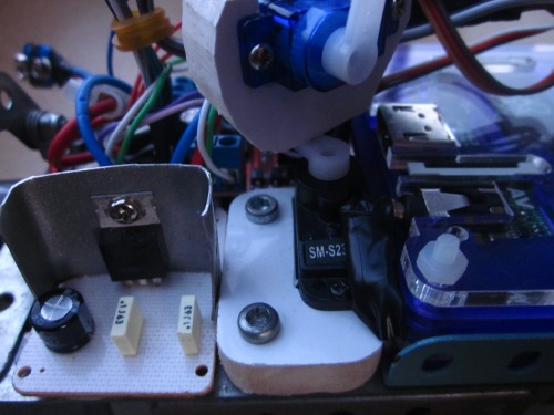 The 5V regulator with my home made heatsink, the pan servo (a good powerful one for it's size) in it's home made holder (made from PVC- great stuff!) with the very weak tilt servo above (I'll probably replace it for another like the pan servo), and the Raspberry Pi looking slick in it's purple case.
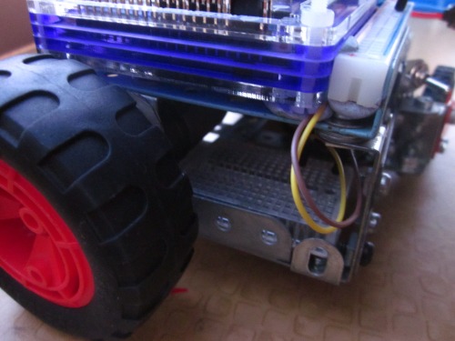 The 170 point breadboard prototyping area. For quick connections or anything that doesn't come in 'module' format eg. the audio amplifier. There is very little space inside the body- the battery pack fits right up against the breadboard and both motors are right in font of both. I was trying to make the smallest robot I could while still making it feature rich. I'm still surprised all the stuff on the top fits together as well as it does. It's amazingly good luck- and something that does not happen very often!
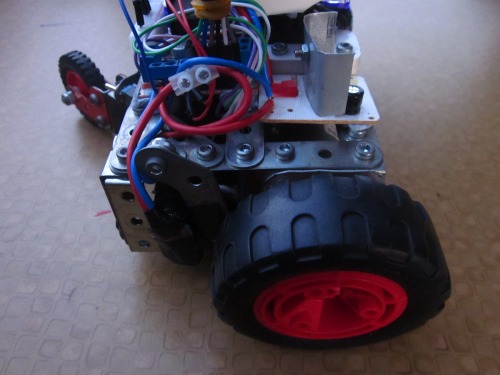 Here you can see the fat battery connector and the little angled piece of Meccano that holds the battery in. It rotates on it's bolt to let the battery out. as you can see there is a little bit of space on the right hand side of the robot, though this is mostly full of wires.
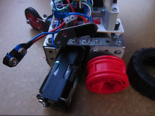 And here is the open battery tray. The stopper is rotated out of the way, the tire is off and then the battery can come free. All the robots I have designed feature easily removable batteries, after I learnt my lesson with the first I tried to make. I did not allow room for the battery at all, so the robot failed. Also, I want to protect the battery and hold it securely but still have good acces to it. This configuration minimises body area lost (and therefore body rigidity) in the exit hole by siding the battery out end on.
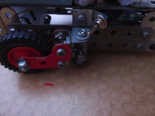 The tail wheel is able to swing approximately 170 degrees. This means turning is of absolute minimum friction. My previous robot had a rigid tail that caused it some dificulty when turning.
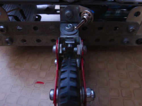 Also, this tail design means the robot packs up smaller. It's only by a little bit, but it looks a bit neater and when you live in a caravan space matters a lot.
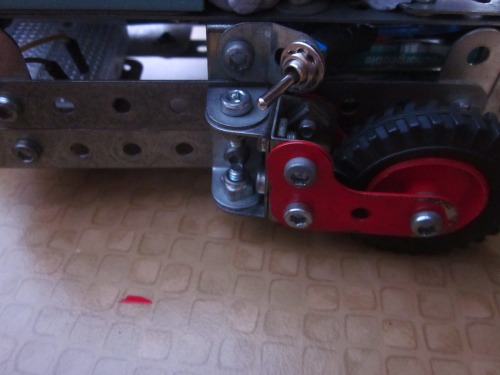 And there we go. It's completed the arc. Fascinating stuff, eh? The only downside is that the robot will have a little difficulty reversing for long periods of time, as the wheel will not stay pointing straight, much like reversing a trailer.
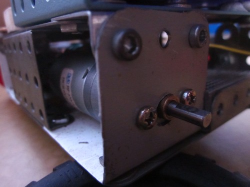 I had to make some custom motor brackets. I'm using two wild thumper motors and needed a way to connect them to the Meccano. The brackets aren't perfect but they do the job well enough. I made them by hand (well, I used a drill, hacksaw and file, a pencil, ruler and snips. Is that by hand?) after getting sick of the little plates (not L shapes) I was using previously.
Well, that just about wraps it up for now. I'll post more info as it develops, but it's a case of balancing life, studies and my hobbies alongside waiting for the next parts to arrive in the post so there's no knowing when the next update will be. I hope you have enjoyed my build. I know I have!
Drives very maneoverably, follows lines, tracks faces, came 5th in Pi Wars 2015. Intelligent obstacle avoidance. Talks using espeak.
- Operating system: Raspbian Wheezy
- Programming language: Arduino, Python, bash
- Sensors / input devices: HC-SR04, 3x ir
This is a companion discussion topic for the original entry at https://community.robotshop.com/robots/show/lobsang

