For my engineering internship, I’m working on designing a flapping wing drone. The idea is to first make a fixed flapping mechanism and find a way to measure the lift (vertical upwards force) generated, as accurately as possible, using an Arduino uno board. The main issue is that since the force is constantly changing direction, a simple load cell could only give the vertical component of the force.
I was wondering if it would be possible to use two load cells (connected to the 2ch shield ( Load Cell / Wheatstone Amplifier Shield (2ch) - RobotShop) to measure the force in two directions and then combine the results to find the "resultant force. Would this be possible?
Would the sampling rate be high enough to model the changing load (flapping frequency of the wings is about 30 hz)?
Alternatively what kinds of sensors would be more suitable considering the wing span is in the order of 10 cm and lift produced is in the tens of grams?
There are very few ornithopter prototypes out there. WowWee commercialized one back in 2006:
There are also bird-like designs:
Some sites have some information:
What you’ll quickly find is that the weight is critical. A full Arduino board and shield is likely way too heavy. The WowWee dragonfly weighed only a few grams with electronics and battery. Without ever having tried such a design, I cannot say what calculations or equations are needed to generate lift.
Regarding the 2ch load cell shield, I’m not sure any load cell you add won’t have an adverse affect on the wing, since it affects inertia, weight etc. You might be better off with an FSR (force sensing resistor), which is analog.
Thank you. Right now the drone is not flying. I just have a stationary flapping wing mechanism and trying to measure the lift. I can’t find any resources on how to code the robotshop 2ch shield to measure the force from the load cell.
Any help with that would be hugely appreciated.
Normally the load cell you use provide the range, so you need to map the max / min analog output with the max/min load cell force (assuming it’s linear). There’s a “map” feature in Arduino. If it’s not linear, then the manufacturer of the load cell needs to provide that data.
I was reading the test procedure manual where it says to adjust the potentiometer on the shield until 338 output. How can i adjust the potentiometer?
I couldn’t find any info on manuals or web.
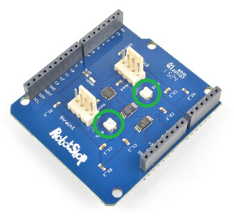
There are two potentiometers on the board which can be rotated using a small screwdriver:
They simply rotate. Not easy finding a video showing it rotate, but:
If it cannot rotate, you’ve reached an endpoint (don’t force it).
Unless the load cell physically changes (for example wear and tear, or something else), you should only need to calibrate once. You would have an initial code to calibrate, get the values, and then the “calibrated code” is what you upload to the Arduino to use for your application.
I’ve been trying to calibrate it but the values i get are really weird.
I put 50 grams and 6 kg and the reading were only different by 2.
I changed the values with the values i got and run the code again and i got values that kept changing, even if no load is applied (was using a single strain with only one load cell).
Any tips?
Sorry but i really don’t know what could be wrong. The load cell was working fine and i also tested the shield which was also working fine.
Can you indicate which load cell(s) you purchased?
The easiest test will be to simply use analog read (there’s sample code in the IDE, though you’ll need to select the analog pin) and see what values you get.
I tried the analog pin but i get always the same values even if a load is applied on the load cell.
The load cell is a simple 20 kg straight load cell from Kiwi electronis.
I used it with the hx711 module with no problem
Can’t find a 20Kg load cell on their website. Has it been discontinued?
If you’re not getting any analog values when the load changes (do verify that you assigned the right analog pins in the code which correspond to the shield), then play with the onboard potentiometer (to ensure it’s not at a max or min), it really should provide variable values.
Although incredibly rare (especially since there’s a QC procedure when they’re manufactured), there’s always a slim chance the board might be defective.
There are two things to play with: The analog input value (which is also affected by the potentiometer setting) and then the equation relating the analog values to the actual force. The first step is to get the max/min analog values based on max/min force applied(according to the manual), then once those are saved, assuming the force is linear, map them to the max/min force to get the actual force value applied as output.


 (fully explained)")