

Here is the video for anyone stuck behind a "Great Firewall"
Overview:
This is a review of the Dagu "Wild Thumper" dual H-bridge motor driver and high-current switch. I will start with a little back story. I came into reviewing this item by chance. I had emailed Oddbot (now working for Dagu) with a story of the excessive problems I was having with my existing motor driver. My robot is driven by (2) DeWalt drill motors, which are clunky and electrically noisy, are hard to stop once going, and are capable of drawing massive amounts of power. I should add that the very high levels of current draw happen only during a stall, with normal "driving around" being in the 6-8 Amp range. Any start-up or direction change that is not "ramped" can double this figure. I told Oddbot of my problems with current draw and the persistent problem I was having with blown FET's. He had mentioned that he had designed a large controller for the Wild Thumper 6x6 platform, that he was curious to see how it would hold up on a different chassis and how it would deal with motors that would pose different demands on the controller. A week later, I opened a yellow DHL bag.
Opening the box:
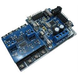
I received this review unit directly from Dagu so I can't speak as to the packaging one would get when ordering from Robot Shop or the like but simply, it was well packaged in anti-static bags with plenty of packaging surrounding it. It came outta the box in perfect condition. My first thought on handling the unit was to remark on how heavy it is. It is slightly larger than a playing card but weighs as much as a large pair of pliers in your hand. Flipping the unit over quickly shows why --the vast majority of the motor driver is all heat sink! Nice big, heavy, substantial heat sink. So far so good.
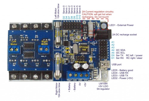
Nuts and Bolts of the Driver:
- 4" x 2 3/8" x 1 1/4" (W,H,Thickness)
- On board Atmega 168 16K (bootloaded with Arduino, (has ISP pins available))
- Dual 15A FET H-bridges with fuse protection
- Blow fuse detection by processor and LED
- (7) General use digital I/O pins with 3-pin "servo" connectors
- (5) ADC inputs with "servo" connectors
- 5 Amp LDO voltage regulator with screw terminals to feed external devices
- 2A On board charging circuitry for (SLA, NiCd, NiMh)
- On board current and voltage monitoring via the Atmega processor
- Communicates via USB, serial, i2c, or PWM "RC servo control"
- Ready for all you AVR people --Programmable via USB or ISP
- Speaks arduino out-of-the-box
- Preprogrammed for use with 7.2v RC packs and RC "servo" control
- Code for "mixing" X/Y into differential drive included
- The Manual is Here
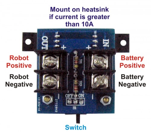
Nuts and Bolts of the High Current Switch:
- 30A+ Switching ability (I really don’t have a spec for this, I’m sure it is much higher than this)
- Small Size (approx) 2 1/4" x 1 3/4"
- “Jumpable” to external switch or TTL control (with transistor)
- Nice big, fat screw terminals for use with “spade” connectors and heavy guage wire
Lets get into it (I love this driver so these will be “Pros”):
I adore this motor driver. --Let’s just get that outta the way. I like the way it looks, I like the exposed glass fuses, it’s got a lot of nifty lights and the big-ol’ heatsink. I love the fact that it has its own microprocessor on board as well as an on board FTDI and thus, USB programming. The charge circuitry works flawlessly and actually charges my battery twice as fast as my “wall wart” charger. The fact that the microprocessor is keeping an eye on the charging process and it is able to communicate to the “main brain” of the robot, makes it wicked easy to incorporate a “charge routine” into your existing code. Voltage level can also be watched and data can also be sent to the main processor. The 5v regulator is a beast at 5 Amps, but the current does become more and more limited as your Vin increases. The code included with the unit is very complete with one exception: I2c communications. The code is simple, clearly written with a logical easy-to-follow flow, with great comments and obvious “sections”. I found it very easy to “strip down” the code to what I needed, and pick and choose what “chunks” I wanted to use. For example, the actual “motor routine” is almost stand-alone, needing only 4 bytes coming in and it works. This allows you to remove it, with little modification, and add it to your control system. Really, it is very nice simple code. I do have to throw in a “however”… However… When you scroll to the bottom of the code, you may be upset to find a comment-line header saying //i2c routine** only to find “your code here” just below it. Hmmmmm.
I like the fact that I have an extra brain doing some of the thinking grunt work on the robot and freeing up thinkin’ space on the main processor. Not to mention simply having extra pins available for accessories. In terms of using this with a Propeller, in addition to a motor driver, you are also getting a 5-channel ADC input chip as well. Hell, you get a 7-channel servo driver as well, if you want. On that note, skip the “main brain” on your robot all together --This one motor driver unit would be happy being the “main brain” of any robot. One more… This is the first time I had brakes available from a motor driver and I will NEVER go back to not having them ever again.
The “Switch”:
I have little to say about the switch. Maybe this is a good thing. I plugged it in, it works great, I have not needed to give it a single thought --it just works. It was a little funny to install as it was designed specifically for the wild thumper, but really, mounting was nothing more than being sure the FET’s (which serve to secure 1/2 the PCB to the chassis) need to be attached to something that can conduct some heat. The switch itself does feel a bit “plastic” and weak but then again, my intention is to jump over this switch to an external one. If one did not choose to do this, the switch is a cheap and easy thing to replace. It appears it uses standard 3-pin .1" spacing.
(This switch unit itself is not quite available --coming soon.)
Why everyone might not like this controller (These would be the cons):
Out of the box, this guy is pretty specific to the Wild Thumper. It is preloaded with software, with the battery pack voltage, max current draw, charge routine and control method already set. It comes working as if it were 2 servos --One would plug their “RC car” style receiver in and the motor driver would use the X and Y of the transmitter’s joystick to control the motors. Now, if one would want to change any of this, even just the method of control, say, to serial input, somewhere along the line, you are going to have to get into some Arduino. We are not talking about any major code writing here, anything you would need to change is clearly marked in the code --the fact of the matter is that you HAVE to do it. If you are not set-up for Arduino, it is going to be a pretty big PITA to download and install the whole Arduino IDE just to change one variable from a 1 to a 2. Same goes for anything else you would want to set: Current-sense calibration, max current levels, battery voltage, etc. all can (but sometimes NEED TO) be changed and this can only be done via the Arduino editor. This is of course, if you don’t intend to rebootload the brain to BASCOM or the like. The bottom line is that you will only see a very small portion of the capabilities of this unit if you don’t speak a little Arduino along the way.
I also quickly found that there is no obvious way to mount this guy. There are a total of 10 holes in this thing, but each one contains a bolt holding a voltage regulator or FET. I suppose, you could remove the (4) bolts closest to the corners, replace them with longer ones and spacers, but great care must be taken that A) the plastic screws remain plastic and B) the insulators under the voltage regulators remain in place. I opted to remove the PCB from the heatsink, drill mounting holes, re-gunk with new thermal stuff and remount the PCB.
The screw terminals are a bit funky as well, sitting in the center of the PCB. This was done obviously for practicality, to keep traces shorter and efficiency higher. I guess I can’t complain, I would rather have function then form. Never the less, a little funky.
There is a small, noticeable “singing” from the driver itself. I did not find it objectionable at all but it is there. I would say that unless your motors are completely silent, as soon as they start turning, you won’t hear the controller noise over them.
Note: I found out the hard way that the FET’s do NOT play nice when you try to run them at 31,000 Hz (the highest you can go when changing the Arduino’s PWM frequency). At this speed, both sides of the H-bridge are on at the same time and well, this is not good. Don’t do this and future manuals will reflect this fact.
Final Thoughts:
The bottom line is: If you speak a little arduino, or are willing to learn the smallest amount of it, this controller completely rocks. You will also be happy if you are a AVR person and program it that way. It is rated and documented (and contains fuses) for use up to 30 Amps total. This is not to say that it could not do much more. Proceed at your own risk, but if you keep a very watchful eye on the heat, you could probably stretch the capabilities quite a bit. It is rugged, ballsy, solid and comes with a ton of bells and whistles.
I hesitate to give anything a 10, but the guy is certainly in the 9++ category. Simply a great controller. Well done.