

map_both.png (50922Bytes)
map_encoders.png (43479Bytes)
map_compass.png (43233Bytes)
047.JPG (1010105Bytes)
052.JPG (1135308Bytes)
Introduction
I was fortunate to be selected by RobotShop to review the LIDAR time of flight distance sensor. This was back in September 2015 and I am 100% to blame for the delay in posting.
Packaging
The LIDAR arrived in a single heavy duty cardboard box with the LIDAR enclosed in a plastic bag and a separate 6-wire interface cable. No hint of packaging problems.
Device Overview
The LIDAR measures distance by measuring the time it take a light beam to reflect off an object. The technology is rather new to the home robot builder and accurate technical details are a little sparse. It takes approx 20 msec for the device to acquire and process a command. I am assuming the 99.9% of the time is doing signal analysis.
The device is smaller than I expected measuring in at approximately 3x4x5 cm. It has 4 mounting tabs and a polarized header for the interface cable. As there were no printed material enclosed, I immediately went to RobotShop for installation, product data sheet, and example code. Was not disappointed and had sufficient resources to get started by following an Arduino demo sketch.
Note: One irritation I did encounter is the 6-pin cable. One wire is RED, all others BLACK.
There are two user configurations available, continuous and I2C. I was pretty sure that I wanted I2C so I did my best to confuse the issue and read all the documentation looking for clues. Downloading and installing the Arduino demo was trivial and I had working results in 10 minutes. Did some tape measure comparisons and results at 1m, 2m, 5m were very acceptable. Walls and ceilings were used to test for longer range targets. All good.
Application
I had a very hard time coming up with an application that would showcase the capabilities of the LIDAR. Saw multiple examples online. Decided that I would try and use the device to map the rooms that are used at the Trinity College Firefighting Contest. I removed the inside walls for this test.
One of the questions that I have not found an answer to is the safe use of the laser. This limited my application to something that would not be harmful to humans or animals. I thought it could be used to detect the mail delivery vehicle.
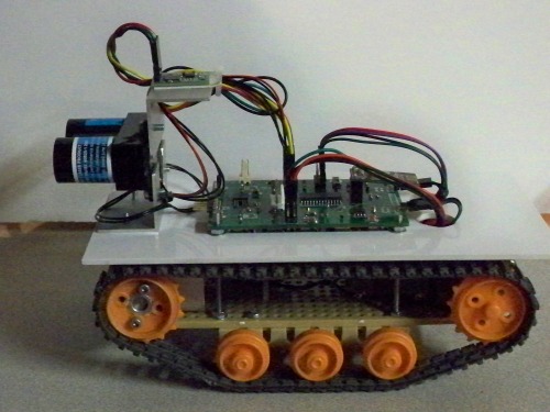
Robot Platform
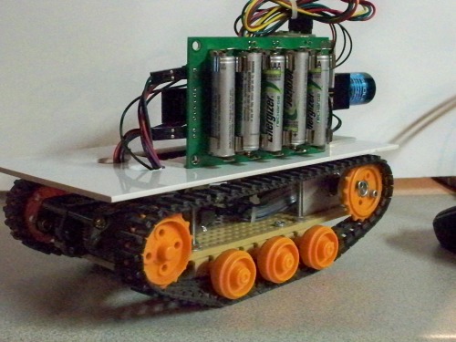
I already had a Tamiya motor, gearbox, base plate, and tank treads wasting away in a project box. I also had just designed a Microchip PIC24 processor board with 2 motor controllers, nRF24L01 radio connector, and 4 AAA battery clips. Wouldn't it be ironic to put a $120US sensor on a $25US chassis. The following are a couple of pictures of the current implementation with the second showing the AAA battery clips integrated on the circuit board.
It did take me some time to get the LIDAR working with my pic24 board. The PIC24 has a very nice selection of hardware peripherals including I2C, SPI, ADC, DMA, etc. I already had I2C working with other devices and just wired up a connector and copied code. Writes to the device worked, reads failed. Quickly abandoned that effort and resume work on Arduino demo code. Immediate success.
This was a good opportunity to try out a very cheap ($10US) Saleae clone logic analyzer with I2C protocol analysis. Quickly detected the problem and confirmed by Google.Turned out that the LIDAR does not support the I2C “RepeatedStart” command. Symptom is writes work, reads fail.
Note: The Arduino I2C library also does not generate or use RepeatedStart.
Solution was to break the I2C read message into two messages. The first being a “Write” followed by an independent “Read”. Nothing disastrous, just another time sink hole. It appears that the LIDAR has 4.7K resistors on the I2C lines. They are not end user accessible without opening the case. I prefer to have 1.4K for 400KHz operation at 3.3V. Adding another I2C device with onboard 4.7K pullups reduces the load to about 2.3K. The Arduino sample code operates at 100HKz and I stuck with that. The I2C signals look like #$%^. Quite surprised anything works. Next revision on my CPU board will contain optional resistors.
Documentation
The LIDAR documentation is overly complex. It appears to be written for experts in laser engineering. The sample code provided more than sufficient documentation to use the device. Spending time learning how the device correlated return data was another time sink hole. I would definitely look further into the configuration options if this device was being embedded in a commercial product. I have noticed occasional large errors that can be filtered in software. There is one piece of documentation that was absolutely necessary and not present in all the official vendor documentation. You need to place a large capacitor on the +5 supply. When the device is active, there is significant noise on the power line. They recommend 670uf. The manufacturer knows it, why don't they add the proper filtering to the device? I currently have about 300uf and the noise is acceptable.
I am also running a CMPS11 at 5V on the same I2C bus and found that I got better results if I waited till the LIDAR is idle. For a while I thought I could get extra compass headings by reading the CMPS11 while the LIDAR was busy. Another sink hole.
Host GUI
A major effort my my part involved making a Linux GTK application to control and monitor the robot.
I use nRF24L01 radios to transmit data to and from the host to the robot. This is not my first experience with these radios but was my most frustrating. It appears that there are bogus clones out there on the various retail sites. Most of my $3.00US modules do not work reliably with my $25.00US genuine Nordic modules. I also wanted error free communications throughout my house, approx 25 meters. I settled for error free from robot to host and limited failures on the host to robot path.
Notes: Clone to clone modules work with each other
Latest purchase seemed better
My GUI allows me to drive the machine forward, reverse, and turn at various speeds while displaying and mapping various parameters. It also supports calibrating the CMPS11 and scanning a room.
The embedded firmware for a room scan pivots the robot very slowly while performing compass and distance readings every 2 degrees based on tachometer feedback. The data is uploaded to the host where the messaged are parsed. Compass heading and LIDAR distance are displayed and if a room scan is active and the points are plotted. Both the tachometer calculated angle and CMPS11 can be plotted. Played with GUI to save and restore data, and replay the scan.
I should mention that compass headings were another massive time sink. I had started with a $2.00US HMC5883L triple Axis Compass. Any tilt or vibration and the results jumped 45 degrees. Went with the $45US CMPS11 from RobotShop because it offered tilt compensation.
Note: The CMPS11 MUST be calibrated at ALL angles and tilts at the run time site.
The CMPS11 appears to be capable of nulling out the effect of the DC motors but driving past any metal structure skews the results. It also appears to not give stable results while rotating. I suspect I would have had better results with a larger more stable platform.
It turns out that the LIDAR might not be the ideal device for mapping small areas such as individual rooms in the Trinity Firefighting maze. At short range, less than 30cm, accuracy seems to be a problem. It is repeatable so it probably can be compensated in software.
Operation
The attached videos show my little robot in a Trinity College Firefighting arena with the interior walls removed. I added a box in a corner and a PVC pipe to test if the scan could detect them. The embedded firmware receives a command to scan the room. In order to let the PID/PWM to stabilize it turns counter clockwise about 10 degrees and then starts the clockwise rotation. When it gets back to zero it transmits a Start Of Message (SOM) packet. Using the quadrature encoder pulse count it samples and uploads a message every 2 degrees. Approximately 2800 encoder tics are a full circle. At the completion it halts the motors and transmits an End Of Message (EOM) packet.
It turned out to be quite difficult tuning the PID for such slow rotational speeds. My encoder also serves as the track front wheel bearing support and gives 64 tics per revolution. The solution was to both count the tics and measure the time between tics. Then average the previous 8 time intervals and use the inverse as PID input. This scheme is not without problems at very short or very short intervals. Quadrature decoded tics are still used for determining direction and distance calculations.
nRF24L01 Data Packets
Each packet contains formatted fields that indicate:
- Command
- Requested speed
- Compass Heading
- Encoder calculated distance
- Motor speed
- Motor PWM value
All numeric data is in hex. I plan on adding additional fields such as a battery voltage.
For transmission optimization I want to migrate to all binary data. The problem is debugging. Right now I can add a third listening only node and easily monitor wireless traffic.
Data packets are received by the host module and uploaded via USB. The application is multi-threaded with 1 thread dedicated to packet reception. Using the GTK library the data is delivered to the appropriate widget for display.
Operational Screen Shots
The following screen shot shows my console upon completion of a 240x240cm room scan. The blue dots represent angles calculated via the quadrature encoders while the red are from the CMPS11 compass.

To better understand the results there are check boxes that enable/disable display of compass or encoder data. The following 2 screen shots show the independent results.


The encoder only frame clearly shows the box and pipe. I use the starting angle supplied by the compass to generate the encoder starting angle. Another large time sink was trying to do a least squares curve fit of the two data sets. Drawing lines with simple filtering also helps but I lost that code.
Videos
The attached videos provide a glimpse of the LIDAR in operation. Not very exciting but getting everything to play nicely was a challenge. The first is the robot in a Trinity College Firefighting basic arena with the interior walls removed and a few peices of junk to add some irregularity. The second is a closeup of the robot rotating quite slowly. And the third is a video of the operators console (sped up 2x).
https://vimeo.com/158379660
https://vimeo.com/158370124
https://vimeo.com/158380101
Conclusion
The LIDAR is a unique instrument that performed flawlessly with little effort on my part. It operates best in a range outside the low cost sonar and IR distance sensors. My total effort probably exceed 500 hours but less than 0.1% of that was related to getting the LIDAR to function, everything else was my own bag of worms.
https://vimeo.com/158380101