LEDs say yes, but Input pins say nothing, or too many things?!

Hi All,

I've hooked up an Optical Mouse to my Arduino Nano, by

- opening the mouse
- locating the IR led and Phototransistor (Dual, which can provide a direction to the scrollwheel rotation)
- breaking off the section of PCB that these were attached to
- soldering wires to the pins of these components
- wired them to the Arduino as follows:

1ytlr8.jpg


I’ve looked at almost every online resource regarding how encoders are hooked up, and tried many different ways, but could not get any successful reading from the serial monitor using Arduino playground code. 

As a last resort, I did the following:

I’ve attached red LEDs (with 100ohm resistors so the LEDs don’t burn out)  into the circuit to check that when i break the IR beam using my finger, or the mousewheel, that the output of the Phototransistor is working.  So far this works, and the LEDs go dark when I break the IR beam.  I just don’t know why the Arduino won’t read this on/off properly.

I think i’ve added 10K pulldown resistors to digital pins 2 and 3 correctly, pulling them to ground.  And I’m using pins 2 and 3 since they are interrupts.

What I can’t get to work is any sort of encoder code.  From either the Arduino playground, or different people’s websites.

Either the serial monitor shows up with no movement, or just keep counting upwards, or counts upwards SUPER fast!  It doesn’t look like the input pins are reading what I want them to.

Can anyone point me to some simple code that will print something in the serial monitor to let me know that the Arduino Nano pins 2 and 3 are getting the signal from channel A and B of the phototransistor?

I’m in the process of trying to build a robot, and i want to use mousewheel-quadrature encoders on the wheels.  I’ve made much progress so far, learning arduino, electronic circuits, components etc…but I am really stumped on this.  Even if someones knows of an C-code, I am willing to venture down the path of learning C earlier than I had planned, just to get over this current obstacle.

Any help would be much appreciated.  I’ve spent several days, and this past entire night trying to solve this and am fully burnt out.
Thanks for your assistance!

Ok I removed the LEDs (and

Ok I removed the LEDs (and corresponding resistors) and got the same Serial Monitor output.  I decided to unhook everything, except for the IR Led, which i know works, and the strange thing is that the Arduino is still giving the same Serial Monitor output, even with nothing connected?!

Heres a code example i tried, followed by the output:

Code:
/* Read Quadrature Encoder
  * Connect Encoder to Pins encoder0PinA, encoder0PinB, and +5V.
  *
  * Sketch by max wolf / www.meso.net
  * v. 0.1 - very basic functions - mw 20061220
  *
  */  


 int val; 
 int encoder0PinA = 2;
 int encoder0PinB = 3;
 int encoder0Pos = 0;
 int encoder0PinALast = LOW;
 int n = LOW;

 void setup() { 
   pinMode (encoder0PinA,INPUT);
   pinMode (encoder0PinB,INPUT);
   Serial.begin (57600);
 } 

 void loop() { 
   n = digitalRead(encoder0PinA);
   if ((encoder0PinALast == LOW) && (n == HIGH)) {
     if (digitalRead(encoder0PinB) == LOW) {
       encoder0Pos–;
     } else {
       encoder0Pos++;
     }
     Serial.print (encoder0Pos);
     Serial.print ("/");
   } 
   encoder0PinALast = n;
 }


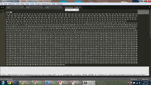
and the output which steadily streams

23v1cmt.jpg


Code example 2

Code:
/* read a rotary encoder with interrupts
   Encoder hooked up with common to GROUND,
   encoder0PinA to pin 2, encoder0PinB to pin 4 (or pin 3 see below)
   it doesn’t matter which encoder pin you use for A or B  

   uses Arduino pullups on A & B channel outputs
   turning on the pullups saves having to hook up resistors 
   to the A & B channel outputs 


#define encoder0PinA  2
#define encoder0PinB  3

volatile unsigned int encoder0Pos = 0;

void setup() { 


  pinMode(encoder0PinA, INPUT); 
  digitalWrite(encoder0PinA, HIGH);       // turn on pullup resistor
  pinMode(encoder0PinB, INPUT); 
  digitalWrite(encoder0PinB, HIGH);       // turn on pullup resistor

  attachInterrupt(0, doEncoder, CHANGE);  // encoder pin on interrupt 0 - pin 2
  Serial.begin (57600);
  Serial.println(“start”);                // a personal quirk


void loop(){
// do some stuff here - the joy of interrupts is that they take care of themselves
}

void doEncoder() {
  /
If pinA and pinB are both high or both low, it is spinning
   * forward. If they’re different, it’s going backward.
   
   
For more information on speeding up this process, see
   * [Reference/PortManipulation], specifically the PIND register.
   /
  if (digitalRead(encoder0PinA) == digitalRead(encoder0PinB)) {
    encoder0Pos++;
  } else {
    encoder0Pos–;
  }

  Serial.println (encoder0Pos, DEC);
}

/
See this expanded function to get a better understanding of the
 * meanings of the four possible (pinA, pinB) value pairs:
 /
void doEncoder_Expanded(){
  if (digitalRead(encoder0PinA) == HIGH) {   // found a low-to-high on channel A
    if (digitalRead(encoder0PinB) == LOW) {  // check channel B to see which way
                                             // encoder is turning
      encoder0Pos = encoder0Pos - 1;         // CCW
    } 
    else {
      encoder0Pos = encoder0Pos + 1;         // CW
    }
  }
  else                                        // found a high-to-low on channel A
  { 
    if (digitalRead(encoder0PinB) == LOW) {   // check channel B to see which way
                                              // encoder is turning  
      encoder0Pos = encoder0Pos + 1;          // CW
    } 
    else {
      encoder0Pos = encoder0Pos - 1;          // CCW
    }

  }
  Serial.println (encoder0Pos, DEC);          // debug - remember to comment out
                                              // before final program run
  // you don’t want serial slowing down your program if not needed
}

/
  to read the other two transitions - just use another attachInterrupt()
in the setup and duplicate the doEncoder function into say, 
doEncoderA and doEncoderB. 
You also need to move the other encoder wire over to pin 3 (interrupt 1). 
*/


The output just prints startCR on the screen and then nothing happens afterwards

Code example 3

Code:
#define encoder0PinA 2

#define encoder0PinB 3

volatile unsigned int encoder0Pos = 0;

void setup() {

  pinMode(encoder0PinA, INPUT); 
  pinMode(encoder0PinB, INPUT); 
// encoder pin on interrupt 0 (pin 2)

  attachInterrupt(0, doEncoderA, CHANGE);
// encoder pin on interrupt 1 (pin 3)

  attachInterrupt(1, doEncoderB, CHANGE);  
  Serial.begin (57600);
}

void loop(){ //Do stuff here 
}

void doEncoderA(){

  // look for a low-to-high on channel A
  if (digitalRead(encoder0PinA) == HIGH) { 
    // check channel B to see which way encoder is turning
    if (digitalRead(encoder0PinB) == LOW) {  
      encoder0Pos = encoder0Pos + 1;         // CW
    } 
    else {
      encoder0Pos = encoder0Pos - 1;         // CCW
    }
  }
  else   // must be a high-to-low edge on channel A                                       
  { 
    // check channel B to see which way encoder is turning  
    if (digitalRead(encoder0PinB) == HIGH) {   
      encoder0Pos = encoder0Pos + 1;          // CW
    } 
    else {
      encoder0Pos = encoder0Pos - 1;          // CCW
    }
  }
  Serial.println (encoder0Pos, DEC);          
  // use for debugging - remember to comment out
}

void doEncoderB(){

  // look for a low-to-high on channel B
  if (digitalRead(encoder0PinB) == HIGH) {   
   // check channel A to see which way encoder is turning
    if (digitalRead(encoder0PinA) == HIGH) {  
      encoder0Pos = encoder0Pos + 1;         // CW
    } 
    else {
      encoder0Pos = encoder0Pos - 1;         // CCW
    }
  }
  // Look for a high-to-low on channel B
  else { 
    // check channel B to see which way encoder is turning  
    if (digitalRead(encoder0PinA) == LOW) {   
      encoder0Pos = encoder0Pos + 1;          // CW
    } 
    else {
      encoder0Pos = encoder0Pos - 1;          // CCW
    }
  }
}


and the output prints really fast


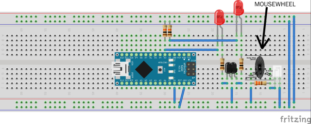
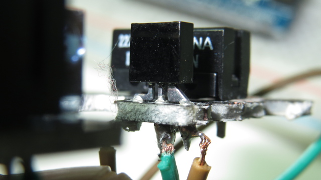
Here’s a photo of the setup, i’ve disconnected the arduino and its really strange why its giving the same output as when I connected the phototransistor.


I can’t find a datasheet for this transistor nor know its model number.  The ones i took out from other mice have EL embossed on the top, which probably stands for Everlight electronics ltd.  This one has LT embossed on the top.

Looking at the leads , i’m now noticing that only one of them is thicker, perhaps this phototransistor is not in the usual pin configuration

2w69kys.jpg


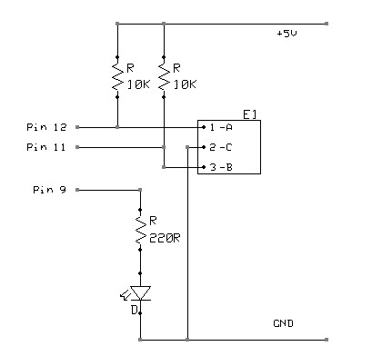
http://www.seattlerobotics.org/encoder/200311/johnson/Mousebot.html
Theodore Johnson explains “The three-pin detector consists of two photodiodes arranged vertically.  The outputs must be pulled to ground by, e.g. a 10K Ohm resistor.” And provides the following diagram:

2mgmp2s.gif


http://www.stevekamerman.com/2010/12/understanding-a-mouse-scroll-wheel/
Steve Kamerman uses a 5 pin unit, where the first 3 pins are for the phototransistor, and the last 2 are to power the IR led

Pin 1: Photo Sensor 1
Pin 2: Vcc
Pin 3: Photo Sensor 2
Pin 4: IR LED +
Pin 5: IR LED -

He comments "There are two 10k resistors. First, connect pin 1 directly to arduino input 2, then put the 10k from ground to input 2. This creates a voltage divider since pin 1 will be slightly positive and the resister will pull it slightly towards ground. Repeat for the other encoder output – pin 3 to input 3, 10k from ground to input 3."

http://www.mcmanis.com/chuck/robotics/projects/lab-x3/quadratrak.html
Here’s an image of a Rotary Encoder setup from Chuck McManis’ site

2mhhovo.gif


http://www.hobbytronics.co.uk/arduino-tutorial6-rotary-encoder
Here’s another setup from Hobbytronics

ibz6sn.jpg


Here’s a pinout of the Everlight Electronics dual phototransistor from the datasheet


I’m also going to stare at the above information long enough, now that its all in one place, and see if the issue will sort itself out that way.  But further help is much appreciated too.  Thanks!

Encoder

1. I like the code in example 3 except using Serial.println from inside an ISR is probably not a good idea.

2. Do you have access to a meter or scope to get a good picture of the actual signals?

IR Led fried via my error

In my most recent breadboard patching manouever, the IR led got connected to 5V without a resistor in series, then I hear a hissing sound and smelled burnt plastic.

On the bright side, I did manage to check if if was working using a digital camera, and it was.  I unplugged the power of the IR Led while still looking into the camera viewfinder, and its glow went off, and then on again when i plugged its power back in.

When I measured the output voltage from one channel of the phototransistor, it seemed very low, 0.5V.  I’m not sure why it would be that low especially when there’s 5V feeding it.  

I think I’m just going to give up on trying to hack the 2 remaining mouses that I have, and get a couple of cheap encoder motors to work with.  At least those will generate the on/off signals that I’m looking for.  

Do you have any theories as to how I can remove this code disc assembly without wrecking the disc?

These Mabuchi encoder motors are approx. $5 on ebay.  But the motor part is a bit too bulky.  I want to attach the code disc assembly to the output shaft of an N20 geared motor.

1_0x0.jpg

The code disc hole is 2.3mm while the output shaft of the N20 motor is 3mm.  So it looks like I'll have to take the code disc to the drill press (at my school) very carefully.  I've seen this device to remove gears, but it doesn't look wide enough to fit around the disc.

EA-063_01.jpg


Anyhow, maybe i'll give this another go after i get a good night's sleep.  Thanks for the help so far!

I only have access to a

I only have access to a multimeter, but no scope unfortunately.  

some progress

Ok now i’m making some progress, yaay!  I’ve checked and double checked, and:


- the IR LED works (tested using digital camera), its being powered by the Arduino 5V (in series with a resistor)

- 5.2V is coming out of the wall adapter

- the wall adapter is powering the Phototransistor

- 2.4V is coming out of the Photransistor when it is in direct contact with the IR Led

- 0.01V is coming out of the Photransistor when I put a piece of paper in between it and the IR Led


So I can finally say that this sensor assembly is connected and behaving correctly.


As for the Arduino…

- Pin 2 (input) reads high/low when I connect it to the wall adapter ground, i guess its floating

- Pin 2 (input) reads low (and stays there) when I connect it to the Arduino ground, so I guess it belongs there.

- no matter where i plug in the 2.4V Phototransistor output, I can’t get the input pin to read it.


I’m just using one output of the Phototransistor to test as of now. I’ve tried Arduino pins 2 and 3 and the behaviour is the same.


Motors with encoders

www.digilentinc.com sells a motor with encoder similar to your motor for US$19.99. Part No 290-006P / 290-008P. While there you can also get motor mounts. Beware, Digilent sells very addictive toys!!!

I’ve replaced the 330ohm

I’ve replaced the 330ohm resistor with a 100ohm resistor which brought the Phototransistor output up to 4.1V, amazing!!!  I tried many combinations of internal Arduino resistor on/off, and external pulldown resistors, and also pulling the Arduino input to either Arduino-ground or the 5V wall adapter ground, but the input either prefers one of the grounds and stays low all of the time, or otherwise jumps around from low to high (floating).


I know I’m very close to resolving this, especially since i’m now dealing with a logic level that the Arduino can read as high.

Have you tried darkening the

Have you tried darkening the enviroment the IR led is in? Due to daylight hitting the sensor, it might throw off the phototransistor. There was anoyther guy experimenting with an IR communications thing and he found that his phototransistor was prone to false reading due to daylight glaring in the photo transistor.