Here I will try to help begginers with the most attractive electronic device the LED. :D
First of all the definition of a LED: An LED or Light Emitting Diode, is as Wikipedia expresses it, a semi-conductor light source. What it does is emit light when a certain voltage is applied.
Well but if you have to connect the LED to voltage then their has to be a positive and a negative on it. YES and let me tell you which is which:

Check the pictures below. There you will see that the positive is the side which isn´t flat. The negative is the flat side is its the shorter lead.
Now that you know how to connect it you need to know how to get your desired current.
This is pretty simple all you need to know is "Vs" stands for Voltage Supply, "VL" for LED voltage, "R" for Resistance and "I" for current.
Now going for the MATHSSS: R= (Vs-VL)/I ------- Resistance= (voltage supply-Led voltage)/current
For Example: Lets say you have a 9v battery and want to power a Red LED. A red LED need 2.2 volts at 20 Ma so calculate your resistor:
R= ( 9 - 2.2 ) / 0.02 = 340 you need a 340 ohms resistor
Now armed with the resistance formula nothing can stop you from lighting all the LEDs you want! :D
If you dont want to do maths or are unsure about your results check this site to calculate your resistors: http://ledcalculator.net/

----------------------------------------------------------------------------------------------------------------------------------------------------------------------------------------------
Quick Tip:
Blue LED= 3.5v White LED=3.5v Green LED= 2.2 or 3v (check which) Red LED=2.2v Yellow LED=2.2v Flashing RGB LED:3v
----------------------------------------------------------------------------------------------------------------------------------------------------------------------------------------------
YOU SHOULD DEFINETELY check out this link if you did or didn´t find what you searched for:
https://www.robotshop.com/letsmakerobots/node/4948 I bet you learn something from it!
Thank you oddbot for this very well detailed tutorial :)
----------------------------------------------------------------------------------------------------------------------------------------------------------------------------------------------
Now lets move on to some simple projects:
LED Light:
Supplies: LED any color, resistor, power supply and a
breadboard
Intructions:
1. Connect your power to the power rails on the breadboard.
2. Connect 1 lead of the resistor on + and the other on the positive side of the LED (the one that doesnt have a flat side)
3. Connect the negative side of the LED to the negative rail
4. ENJOY!
Now keep experimenting until you feel pretty confident about how to wire LEDs
----------------------------------------------------------------------------------------------------------------------------------------------------------------------------------------------
Let´s move onto some harder LED circuits:
A simple Dark activated LED flasher:
Supplies:
Transistors: 2n2907, 2n2222 Resistors: 1k, 2m Capacitor: 1uF an LED and a LDR (Light Dependant Resistor)

R1 & R2 stand for Resistor 1 & 2, Q1 stands for the LDR, C1 for Capacitor and Q2 and Q3 are the transistors.
The LED flashes when the LDR is iluminated, when the LDR is dark the LED is off,also the capacitor controls the flash rate.
----------------------------------------------------------------------------------------------------------------------------------------------------------------------------------------------
Programmed Project:
In this one I´ll show you some basic PICAXE programming to make a LED flash without using a Capacitor like in the previous project
First of all you need a PICAXE IC, I am using a PIC 28x1 but I believe you can use others too the only thing diferent is the pinouts.
Supplies:
10k resistor, 1k resistor, PICAXE IC, Breadboard, a push button and Picaxe project board (you can also hook up the IC directly to the breadboard if you want to)
First lets go through the wiring:
1. Place the push button on the breadboard, half on each side (see picture)
2. Connect one lead of your 10k resistor to ground and the other to one pin of the button
3. Connect the voltage diagonaly to the pin of the button connected to ground
4. Place one lead of the 1k resistor on the same row the ground connected to the button is and the other lead connect it to Input 0 of the PICAXE
5. On the same row where you did the connection to the input 0 add 1 lead of a 330 ohm resistor and the other to the + led of the LED you want to use.
6. Connect the LED to ground.
7. Add this program to the programming editor:
main:
if pin0 = 1 then ledon this tells the PIC to read pin0 and then go to ledon if it has voltage<br /><br />if pin0 = 0 then ledoff if pin0 has no voltage then go to ledoff
ledon: high 2 gives pin 2 power to light the LED<br />high 2<br /><br />pause 100 this is the time before checking pin0 again, when button is kept pressed this regulates the flash rate
ledoff:low 2 tells the PIC No power to pin 2<br />low 2<br /><br />pause 100<br /><br />goto main after going to either ledoff or ledon this tells it to repeat
8. Once you added the program, keep the button pressed and see the LED flash 
(such a big walthrough to see a LED flash…)
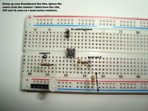
If you cant read the descriptions right click the image click see image and when you are on another page ctrl + it to zoom
----------------------------------------------------------------------------------------------------------------------------------------------------------------------------------------------
Youre still not convinced that LEDs ain´t fun? Then check out this posts:
The other use for LEDs (thanks to rik) :
https://www.robotshop.com/letsmakerobots/node/3518
LEDs making your night a happy one (thanks to Geir Andersen) : Variants of this project by inoblegnome and nuumio, thanks!:
https://www.robotshop.com/letsmakerobots/node/17532 https://www.robotshop.com/letsmakerobots/node/22527 ( by inoblegnome)
https://www.robotshop.com/letsmakerobots/node/19149 ( by nuumio)
LEDs keeping your feet safe at night (thanks to isotope) :
https://www.robotshop.com/letsmakerobots/node/18524
A pretty COOL synthesiser (thanks to Telefox) :
https://www.robotshop.com/letsmakerobots/node/17166
https://www.youtube.com/watch?v=VPVoY1QROMg