I am the proud owner of an uBotino board by Robot-x. I do not own a USB-to-Arduino cable (FTDI with auto-reset). However, I do own computers with good old fashioned serial ports.
So I think I'm gonna build a serial programming circuit. Would the classic "Picaxe" level-correcting schematic work in this case?
That's: * a voltage divider to shift down the signal from my PC from ca 11V to 5V; * a series resistor in both data lines to limit current;
And what about the auto reset? Is that just a matter of connecting Arduino's RST to PC's DTR? Should I protect that current as well?
Update 16 March 2011.
So I designed, built and failed. Or rather, lost patience. I learned a lot though, so I am calling it a victory. A victory over my problem (I know it now, I know how to solve it, I now know my board fabricating is crap.) but also a victory over my own stubbornness.
So I caved, big deal! Here are three boards that should be able to program a uBotino. Or any Arduino that has no on board ftdi.
- Home built level converter using a PNP-NPN pair of BJT's plus another PNP for auto reset feature. - Same thing designed by professionals, soldered by me. No auto reset though. - USB serial converter with FTDI, with auto reset feature. Requires special drivers in my OS. Comes ready made. Is tiny.
Rik, here is a schematic I have used to program my first Arduino compatible boards, before the FTDI cable came out with their specific pinout. I was using a MAX232 level converter for Tx, Rx and Rst pins from a DB9 serial connector. The pinout of the 5 pin connector at the left of the schematic is as follows:
pin 1 - GND pin 2 - Vcc (5V) - provided by the target board, not from the serial port pin 3 - target board Rx pin pin 4 - target board Tx pin pin 5 - target board Rst pin
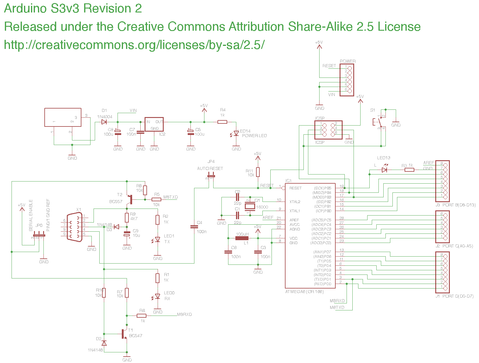
If you look online at the original serial Arduino schematic, you will see that they used transistors for level conversion, I never tried this, but it works for sure. Build with what ever you have handy.
Note that the two resistors are not a potential divider. The 22k resistor works with the internal microcontroller diodes to clamp the serial voltage to the PICAXE supply voltage and to limit the download current to an acceptable limit. The 10k resistor stops the serial input ‘floating’ whilst the download cable is not connected. This is essential for reliable operation.
Hmmm. The plot thickens and the likelihood of this scheme ever working verbatim on an arduino thingy shrinks. Time to start improvising and experimenting. 8-D
■■■■■ I totally forgot: RS232 uses negative voltages. I don’t think Arduino chips will accept that. The voltage dividers work beautifully by the way. -12V is nicely shifted to -4.27V…
Yeah you read that right: negative. Those Picaxe boys really have got it goin’ on for themselves!
The diode/cap provide a steady negative voltage supply, so that the circuit can produce negative voltages in order to signal from TTL uC to RS232 PC. The positive signals to the PC are “only” Vcc (+5V in my case), but most current PC’s will accept that as a distinct signal. Even though dinosaurs once designed it to be higher than that, because they were running much longer cables than us.
The article does not explain the use of a diode (D2 in your circuit) between the base of the PC-to-uC-transistor (T1) and GND . The Sparkfun version has a pull down resistor (R2) instead. Perhaps a diode provides a cleaner signal than a resistor?
I refuse to build any circuit from scratch that I do not design myself (or at least fully understand). I might as well just buy a ready made solution off the shelf. Which I often do in daily life. This is not daily life. This is my hobby. My study. These are all my LMR. These must all belong to us.
Rik, I can’t explain how the transistor circuit works, as I never bothered with it. I always used a MAX232 for my circuit. Anyway, if you want, I can mail you a USB-serial cable, already converted to work with the uBotino.
If I can’t get it to work, I’ll get the Sparkfun convertor. Or a proper all purpose USB-ftdi-TTL thingey. Like I said before: I want to “own” the design mentally. I may be cursing, but I’m cursing my way to self sufficiency.


