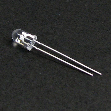
So, I bought from an online shop an IR LED and an IR receiver, like this:
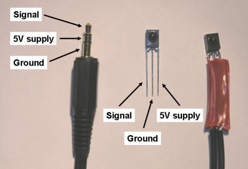
and I want to connect it to a Picaxe chip, but I don't know how. I found plenty of tutorials about this one
like this:
but no information about mine.
Could anyone help, please?
Wrong Tutorials…
I dunno 'bout this headphone jack tutorial you found. This would lead me to believe you would be plugging this assembly into the “sync jack” of the picaxe board. You should not do this.
Instead, I would go straight to the picaxe manual(s) and connect all this in the way described by the picaxe people. To be honest, I would be curious how you arrived at this headphone-jack technique… …If one were to google “picaxe IR”, the vast, vast majority of links are to the proper way of doing this --where did you find this headphone system?
Jack
No, the image with the jack is wrong
I posted it just for the informations(gnd, 5V, signal) about the sensor(as an example), but what does interest me is the one in the first image, the one with only 2 legs. It is not a LED, it is a receiver, I don’t know how to connect it.
I am starting to catch on a bit…
And I think you really should hit the manuals a bit --they are really clear on this one.
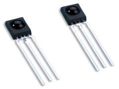
Ok, you have 2 different sensors there. The 3-pin sensor is not only an IR sensor, but has some brains stuffed into it as well. This is the “standard” sensor to be used with TV remotes (typically the “Sony IR Protocol”. This sensor, when connected to the picaxe via the “picaxe IR circuit”, will catch transmissions from TV-style remote controls, send the series of bits to the picaxe, and the picaxe will then spit-out a number that relates to that particular “command” from the remote. If you want to transmit something from a picaxe (use the picaxe AS the TV transmitter), you would need a IR LED and small resistor.
The sensor you are showing with the 2 pins (the one that looks like a LED) is indeed a sensor. It is actually a photo transistor and will react to IR light. This sensor is not typically used to send data (although it can). Instead, this kind of sensor is usually used in conjunction with a IR LED. The light from the IR LED would either be shined at the sensor so one could tell when the “beam is broken” --or-- it can be used with the IR led and sensor side-by-side. In the side-by-side configuration, you would be reading the amount of IR light bouncing off an object and returning to the sensor. Note, this “bouncing” system will only give results at very close range.
If you are curious about playing with your sensor, you should check the manual for connecting LDR’s and also Transistors (it will be similar to both). You will need to construct a circuit including a pull-up resistor on your sensor so your ADC can properly read it.
Lemme know if any of this makes sense, I can go into further detail about the circuit if you need it.
thank you Chris for helping
thank you Chris for helping me, I really appreciate that. I read the manual and I found what I need, so it is okay.
cheers 


