Hey LMR:
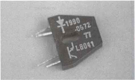
Has anyone used these?

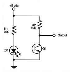
Calculon picked up a bunch for cheap, but hasna figured out how to work it. His is an l7819, though. He's wired it up like so:

Which doesn't show any kind of result. Any ideas?
Before you ask: yes, calculon is a friend of the Google :>
I’ve used angled IR
I’ve used angled IR LED/Phototransistor pairs like that before, they’re more or less the same as the popular QRD1114, just in a different housing.
Not sure why yours isn’t working, the diagram looks fine… ~50mA through the IR LED, Q1 should be able to drop at least a volt across that 10kΩ resistor when it saturates (0.1mA Icesat is a common minimum)…
My only suggestion is to check your pins, make sure it’s wired up right. If possible use a digital camera to see if the IR LED is actually on; if that works you know the problem is in the phototransistor half of the circuit.
Octopart doesn’t have the l7819 listed, so I can’t help you much with any further specifics =/
Optocoupler?
What you might have there is an optocoupler, also called an opto-isolator.
You would typically use this if you want to have one signal (through the diode leads) trigger the photo transistor, but stay electrically isolated. The diode is actually an LED that triggers the photo transistor.
The circuit you show would always turn the LED on, which should trigger the photo transistor and connect the output to ground. If you insert a switch between the +5V and R1, it should operate like a logical NOT gate. Turning on the switch will turn on the LED, which will give you a logical low on the output. Turning off the switch will allow the output to float high through the R2 pull-up resistor.
If that doesn’t help, can you confirm that you are getting current through the LED portion of the component. It may only be 10-20 mA. 70 ohms may be a little low, depending on the forward voltage of your LED. If you passed too much current through the LED, you may have burnt it out. Start with a higher value, maybe 1k, and work down.
Does the output section (the photo transistor) of your component have 2 or three leads? It looks like two, but the picture is a little blurry.
Try bumping up the resistor
Try bumping up the resistor to even 100k on the transistor, as coupled saturation values can be somewhat low. When the transistor is off, with nothing reflecting or over a black, absorptive surface, the output should be high, near 5 volts. When a reflective surface is near, the output should drop to 1 volt or less, perhaps 0.7 or even 0.3.
And detection distances can be very small. Have a very white surface within a millimeter of the LED and sensor to check, and try moving in or out slowly to see if detection changes.
D or A?
Are you using a digital or adc input? If it’s digital, that’s your problem. I use mine with digital inputs but I really had to play with different values for the pull-up resistor. Try the same system on an adc pin and use the numbers coming back to help you find out what resistor you need.
The IR LED/Phototransistor
The IR LED/Phototransistor pair in the photo isn’t the same as Calculon’s, but similar. Standard 4 pin arrangement.
Also IR LEDs have a typical voltage drop of 1.2V and forward current capacity of 50mA, so 70Ω is probably ok. A little lower would be safer, but you want as much current as possible to increase the sensitivity of the device.
This device seems to be the
This device seems to be the same as the QRB1134 which I recently hooked up. I used a setup identical to yours except that I used a 220 Ohm resistor instead of a 70 Ohm resistor. It works for me.
And as Chris above said try starting out by connecting it to an ADC. Perhaps see what the analog readings look like in an oscilloscope…
ah-ite
Calculon has only tried it on adc, and gets the same readings if the thing is connected or not (which is to say a fluxuating reading between 0 and 10). He’ll try different resitor values, but if this thing only has a detection range in the milimeters, he’s not really interested in it anyway.
Thanks for the input, fellas. you are competent and talented people.
Hmmm…
"…gets the same readings if the thing is connected or not (which is to say a fluxuating reading between 0 and 10)"
Are you sure? When I first connected the thing I also got what looked like random fluctuating readings, kinda like when you read the ADC with nothing connected to it.
I wasn’t until I saw the readings in an oscilloscope that I realized they were in fact quite different…
Anyway it DOES only have a range of a few mm’s so you’re not interested 
Perhaps you’re looking for a SHARP sensor instead?


