The 2 diagrams are cicuits for driving led at 38khz. I implemented both circuits. Firstly i take the second cicuit from the link and just add on the transistor part as seen in the first circuit. I did not add the 4.7kohm resistor nor did i add the 47ohm. Is that the reason why six of my leds are blowing out?
OR
the circuit over here http://marwww.in2p3.fr/~levansuu/projets_es2i/Parallax/stamps%20in%20class%20website/downloads/rob4.pdf
Either will probably work
Either will probably work fine, but I’d go for the 2nd option since they’re actually using the discharge connection.
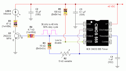
You can use a transistor driver like in the first example if you need more current for your LEDs (especially since IR LEDs are often rated at up to 50mA instead of the usual 20mA).
Whats so significant about
Whats so significant about the discharge line? anw, it has less components so i would be going for that. The main problem is the 6 IR leds i have to drive, any circuit for that?
The discharge line exists
The discharge line exists for the designated purpose of discharging the timing capacitor, so it makes sense to use it for that, even though the 1st design you posted does not.
The transistor LED driver from the 1st design is fine for driving your IR LEDs, just make sure the choose the resistors to match the voltage drop/forward current for your particular LEDs, and that the transistor has a high enough base current to handle all 6. You could have all 6 LEDs in parallel, 3 lines with 2 LEDs each or 2 lines with 3 LEDs each, up to you.
Still looking for help?
Are you still looking for help on this? Is that why you posted “new”? To refresh this to the top of the recent posts?
If your IR LEDs are blowing, the chances are that you are pushing too much current through them, or installing them backwards.
If you didn’t limit the current with resistors, that would explain it.
If all you are trying to do is run a IR LED, you may not need the additional current from the 2N2222 transistor. The 555 timer should be able to source enough current to run an LED directly.
Just verify the voltage drop across the LED, subtract that from the logical high output voltage level from the 555 and that gives you the voltage across the current limiting resistor. Then pick a small current (like 20 mA) that you want to limit to, and use Ohm’s Law to select the resistor value.
R = V / I (resistance equals the voltage divided by the current)
Example:
Voutput = +5V
Vdiode = 0.6V
Vresistor = 4.4V
I = 20 mA (0.02 A)
R = 4.4V / 0.02 A = 220 ohms
A little confused with the
A little confused with the last part. I figured that I needed the transistor because i will be runnning 6 ir leds. so thats why. How do i calcultate? Confused.
More help
So you want all 6 IR LEDs to pulse at the same frequency at the same time?
Also, do you have the specifications or model number for your IR LED so we can know the voltage drop and recommended operating current? If you are not sure, the voltage drop for a gallium arsenide IR LED is typically 1.2 to 1.3 volts. Typical drive current is 50 mA.
Maximum output current for the 555 is 200 mA, but you’ll want to stay well below that if you can. So you will need to boost the current as you said.
With a 1.2 volt drop for each LED, you could run them them with two parallel rows of 3 series LEDs each. Each parallel row would drop 3.6V, and you want to size a current limiting resistor in EACH row that will be about 50 mA.
Actually, breaking it up
Actually, breaking it up into two parallel legs of 3 LEDs does get you down to about 100 mA, so you might be able to do this without the transistor after all.

By the way, does anyone know
By the way, does anyone know how to measure frequency?
Your mulitmeter might have a
Your mulitmeter might have a setting for it. Or you could get/make a simple logic analyzer or frequency counter with a micro.
Just program a micro to count highs on a pin for a certain time period and maybe serial print it or display it on an LCD.
My multimeter doesn’t and I
My multimeter doesn’t and I don noe how to do it with a micro. D; U noe how to do it with a bs2?


