Inverse kinematics

Hmmm… Allthough I would

Hmmm… Allthough I would have liked a bit more info from MarkusB I think he did have a point. I was also thinking about using vectors and HOW. To represent the limbs? the movements of fixpoints (and if so then which)? OR indeed both? After googling some more I see that you can also use vectors to represent the axis of the servo, which I don’t see the point of at all :confused:

Oh well gotta keep reading…


You won’t need linear

You won’t need linear algebra for the individual leg, but it will come in handy when you want to move the leg relative to other things than its base. For instance, you will want to move the leg in an arc arund the center of the robot to have it turn in place. Or you witll want to rotate and tilt the robot’s body. Then it’s much easier to simply use a matrix to convert from one coordinate system to another, relative to the (rotated) robot’s body.

Picture

Thanks for posting the picture. It would be easier for me to communicate if the angles were named in computer language notation.

I don’t think it matters much if you call it geometry, trigonometry, vectors, or linear algebra. They are all tools to help you analyze the problem and formulate a solution. I suspect the choice is very much dependent on your background, associates, and willingness to experiment with different methodologies.

Question for group: These equations are relative to the center of rotation of the hip joint. Don’t we need to account for the center or zero point of the whole beast?

My hexapod never worked well and I have taken it apart for upgrades and not yet put it back together. Perhaps this project will inspire me to get going. Please continue to publish results and make me feel envious.

I still think it may be

I still think it may be advantageous to use vectors to represent the leg segments, as well as the movements, even though it’s not necessary. But I’m still not sure.

And like Duane and Deshipu both mentioned I too think it’s necessary to operate with several “coordinate systems”. I think the following would be a minimum:

(1) The “world” (i.e. the cartessian space in which the critter moves).
(2) One relative to the (center of?) the robot which is needed to coordinate the movements of the legs in conjunction.
(3) One relative to each leg which is needed for calculating the individual leg’s movements.

Perhaps it’s even better to operate with a “coordinate system” for each joint/leg segment?

Another thought… In the drawing above (and many others I’ve seen) the only end point is the foot §. But wouldn’t it be necessary to operate with another end point, namely where the leg is attached to the body? I mean sometimes this is the point you wish to move, e.g. when you want the body of the robot to tilt, twist or sway in order to move the center of gravity of the robot, which is necessary (for quadrupeds) before lifting a leg.

BTW here is another article about IK that may be of interest. Also the PDF from which I got the drawing and formulas in the topic description has a large chapter about Kinematics in general before mentioning IK. Still haven’t understood it well. Perhaps you’ll have better luck.

You get the other point for

You get the other point for free from the same formulas, because the position of the end of leg relative to the base of the leg is the same, except reversed, as the position of the base of the leg relative to the end of the leg. You just flip the signs.

Hey deshipu,I don’t quite

Hey deshipu,

I don’t quite understand how you’d use a matrix to convert from one system to another. Could you elaborate on that?

Just thought I’d share this

Just thought I’d share this amazing PDF. It should be interesting to everyone who’s into walking machines. It was named as source 1 in the PDF I mentioned earlier, from which I got the drawing and formulas in the topic description.

Now this new PDF actually doesn’t touch the subject of IK, BUT it has a very thorough explanation of forward kinematics, including translation from one system to another, using a rotation matrix.

Ah in both PDF’s they use the word “frame”. From what I gather this word is used to describe what we so far have called the individual coordinate systems (e.g. world, robot, leg). Is this a correct assumption?

Besides that this PDF has a lot of interesting info. For instance:

“Theoretically the total number of possible gait event sequences for a quadruped is 5040, but only a very small portion of them are suitable as gaits and used by animals…”

“Of all 5040 different possible gaits for quadrupeds, there are only 6 that allow the animal to have three legs in ground contact at all times. McGhee, and Frank (1968) showed, under somewhat restrictive conditions, that three of these six gaits were statically instable and one, the crawl gait, maximizes the stability margin…”

:smiley:

This looks interesting,

This looks interesting, thank you!

Ah BTW I found this math API

Ah BTW I found this math API for Python. It does vector/matrix-math very well apparently. Check it out…

NumPy and ScipPy are very

NumPy and ScipPy are very popular in any scientific use of Python, and rightly so. Practically all scientific libraries, from bioninformatics and biochemistry to physics and astronomy use them. There is even a separate conference for their users!

Yes it seems pretty cool.I

Yes it seems pretty cool.

I started plaing around with VPython and I decided to use that due to it’s simplicity. And it turns out that NumPy is actually an integrated part of VPython.

This paper is really great!

This paper is really great! Not so much because of what they discovered (I didn’t even get there yet), but because it has a very nice summary of what is known so far about quadruped static gaits. I’m in the second chapter and I’ve already found a lot of stuff that I had to learn the hard way myself, plus a lot of stuff that I didn’t know and that I will have to try with my robots. Also a lot of ideas for what can be improved. Thank you.

Yeah it’s awesome.I think

Yeah it’s awesome.

I think these subjects have a very steep learning curve because when you google it a lot of the entries are written by amateurs who may know stuff, but lack the methods of describing it systematically. Other entries on the other hand are written by people who do, but they are experts writing for other experts, and therefore very hard to understand.

What I like about this paper is how thorough it is and at the same time extremely well written and (for the most part) easy to understand, because it explains everything step by step very systematically, and without presuming too much about the reader.

As I mentioned I want to

As I mentioned I want to create a 3D model of my robot to help me understand and visualize the math better. The idea is to end up with an application that besides being the brains of the robot, also visualizes the robot itself, as well as the sensor data.

Last night I was playing around with Visual Python and made this:

crab_model.png

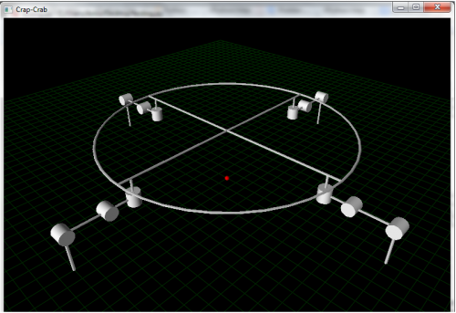
It ain't pretty :) But it isn't supposed to be. I wanted it to be as simple as possible. I didn't use modeling software, I simply draw 3D primitives (lines, cylinders, ring) onto the screen using code.

The idea is to use vectors to represent ..well.. everything. E.g. each leg segment is represented by a vector, and the leg is then drawn onto the screen based on this vector. There will also be a vector representing the axis of each servo (the cylinders). This way when I wan't to move a servo I simply use the function rotate() provided by VPython. E.g. if A is the leg segment vector, B is the servo axis vector and I want to rotate theta degrees, I'll simply write: A.rotate(theta,B). And that's it.

Also if I want to know the position of the end point (or any other point) of a leg given the servo positions (aka Forward Kinematics), it's simply a matter of adding the leg segment vectors up to that point. E.g. if A is the coxa, B the femur and C the tibia, then the simple vector sum A+B+C would give me the end point position.

As mentioned before I'll be using different frames. One for each leg, one for the robot itself and the "world" frame. As it turns out translating between these frames is actually pretty simple (if I understand it correctly), using a translation matrix:

trans_matrix.png

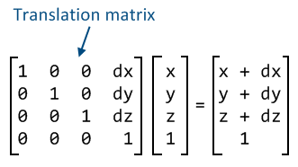
For instance the leg segment and servo positions are given relative to the leg frame, and the leg position relative to the robot frame. If I want to know the leg segment and servo positions relative to the robot frame, I simply solve this matrix with (x,y,z) being the respective positions of leg segments and servos relative to the leg frame, and (dx,dy,dz) being the position of the leg relative to the robot frame. And that should be it.

There are still several things I'm having trouble wrapping my head around though. For instance... in Forward Kinematics you always have exactly one solution. But in Inverse Kinematics you may have no solution or many/infinite solutions. Not sure how to manage this yet?!

Anyway that will be it... for now :P

To Deshipu:It would seem our

To Deshipu:

It would seem our projects are somewhat similar. We`re both making a quadruped of similar configurations. We both wanna use a Python application as the brains of the robot, sending instructions and receiving sensor data to/from the Arduino. And we both want this application to visualize different sensor data.

Anyway we could, as far as the Python application goes, make this a joint venture. This off course would require a certain amount of communication/coordination, so I’m not sure to which degree we should develop together or simply share code/ideas. Either way I’ll create a blog for this project and will be uploading my code there regularly.

Collaboration

It’s complicated :slight_smile:

On one hand, I do want to make a general-purpose python library with different gaits that you could use to control your robot. I even started on it already, it’s called pyambulate and so far only has the basic creep. I hope to get it to a state in which it is stable enough for collaboration, but I’m afraid that the paper you linked will make me change a lot now to make it more general. In any case, this is a good project to collaborate on, I think, once I make a release.

I would also be happy to use the visualisation software that you are developing, and I’m sure I would contribute to it wherever I see the opportunity – just put it on github or bitbucket, and then you can accept or reject patches.

On the other hand, I don’t know where I want to go with my robots and what I want to do with them exactly. I’m just having fun playing with them, and implementing random ideas. I don’t want a more rigid approach, because I’m afraid that it would bore me and make me do something else. I do have ideas for trying different robot configuration, in particular a crab with 2DOF legs that would still use inverse kinematics, and a 2DOF quadruped in the mammalian configuration. But I digress. I don’t want to collaborate on that. I also don’t want to make any promises, or take any responsibility. This is my hobby project and I don’t want it to become a burden.

I hope you don’t mind me being honest about it.

1st off… Honesty rules, so

1st off… Honesty rules, so off course I don’t mind :wink:

2nd… It was never my intention to intertwine our respective robotics activities completely. For me this is also just fun, and I wouldn’t wanna make too many promises or adapt a more rigid approach. God forbid :smiley:

However it could perhaps be beneficial to us both to find some level of short term coorporation regarding the BASICS of the Python control application. This application we could then take separate places, yet still share code easily (no strings attached) given the common starting point.

The 1st thing would be identifying what “the basics” mean. It could be simply agreeing on a common approch, such as described below with a separate frame for each leg, the robot and the world. And agreeing on where the origin of the respective frames would be. It could also be finding a general (easily configurable) format for the serial communication. Or agreeing on certain configuration constants in general (e.g. I allready made the length of the respective leg segments configurable).

I actually don’t know right now, but small things like this would allready facilitate sharing code (e.g. a gait), without actually coorporating, in the future.

Anyway we’ll see how things work out :slight_smile:

As mentioned I wanna create

As mentioned I wanna create a Python application that visualizes the robots movements. I started by creating one for the kinematics (forward + inverse) of a leg.

leg.png

The idea is that the user can enter an angle for each servo, and the program calculates and shows the corresponding leg movements (aka forward kinematics). Or the user can enter the coordinates of the foot and the angles will be calculated based on that (aka inverse kinematics).

So far the forward kinematics work pretty well, but I'm having problems implementing the inverse kinematics using the formulas above in the topic description. Calculating gamma works fine (with a little twist), but alpha0, alpha1 and beta return some strange values that I can't make sense of.

I know it's a long shot since running the program requieres VPython (which probably very few here have), but if someone can see what I'm doing wrong it would be awesome, so I uploaded the code to here. Most of the code is irrelevant though (creating user interface and drawing, etc.). The function in question is called calc_inv(). Here is the part that implements the formulas:

# Calculate c (gamma)
c = 90
if z > 0: c = degrees(arctan(x/z))
elif z < 0: c = 180+degrees(arctan(x/z))

# Auxiliary calculations
h = abs(y)
h2 = h*h
l = sqrt(x*x+z*z)
k = (l-COXA)*(l-COXA)
fem2 = FEMUR*FEMUR
tib2 = TIBIA*TIBIA

# Calculate a0 and a1 (alpha)
a0 = arctan((l-COXA)/h)
a1 = arccos( (fem2+k+h2-tib2)/(2*FEMUR*sqrt(k+h2)) )

# Calculate b (beta)
b = arccos( (tib2+fem2-h2-k)/(2*FEMUR*TIBIA) )

I should perhaps mention that I'm working with a different coordinate system than that above, meaning that for me the x-axis is horizontal, the y-axis is vertical and the z-axis is the depth. That is why y and z are interchanged in my code.

Use a repository

I really recommend to use a code repository right from the beginning. You can put it on bitbucket or github and not only easily link to your code and to its individual lines, but also receive pull requests with proposed changes, and discuss individual lines of code in those. You will also have a full history of your code’s development, and you will be able to always get back to a working version. Not to mention a backup, in case something happens to your computer. It seems complicated, but to start you only really need to know three commands: init, commit and push.

As for your formulas, the way they are rolled all rogether into a single formula makes them rather hard to understand and analyze. Have you tried my code? You are free to use it.

I tried analyzing the

I tried analyzing the formulas and came up with something like this:

import math

def _solve_triangle(a, b, c):
a, b, c = abs(a), abs(b), abs©
if a + b < c or a + c < b or b + c < a:
raise ValueError(“Impossible triangle: %r, %r, %r” % (a, b, c))
cos = float(a ** 2 + b ** 2 - c ** 2) / (2 * a * b)
return math.acos(cos)

def _norm(a, b):
return math.sqrt(a ** 2 + b ** 2)

j = _norm(x, y)
k = j - coxa
d = _norm(z, k)
sigma = math.atan2(x, y)
alpha0 = math.atan2(k, z)
alpha1 = _solve_triangle(d, femur, tibia)
beta = _solve_triangle(tibia, femur, d)

Please note, that it doesn’t correspond to those formulas exactly – I think he made a mistake assuminig that (a + b)² == (a² + b²), but I’m not sure.