

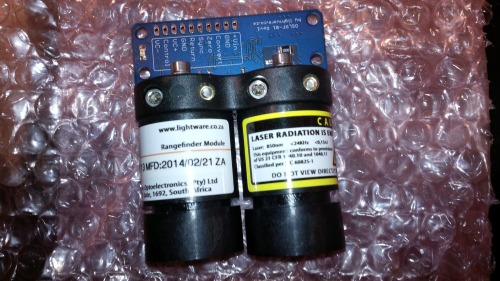
So I received this awesome package in the mail yesterday from LightWare Optoelectronics in South Africa.

I had posted a link here on LMR last week to highlight this new product that had been developed for the Hobbyist / Open Source Community. Open source laser rangefinder sensor. up to 9m $100USD
Open source laser rangefinder sensor. Including optics, laser, detector, amplifiers and sequential-equivalent-time-sampling (SETS) circuits, it is a 'bare-metal' front end component for a laser rangefinder system. Now available.
- Range :: 0.5 ... 9 m
- Resolution :: Adjustable
- Update rate :: Adjustable: 3 ... 50 readings per second
- Accuracy :: Adjustable
- Power supply voltage :: 12 V (10 … 16 V)
- Power supply current :: 50 mA
- Outputs & interfaces :: Timing & laser signal outputs
- Dimensions :: 27 x 56 x 65 mm
- Weight :: 57 g
- Mounting :: 4 x M3 (3.2 mm diameter)
- Connections :: 0.1 in. pitch header
- Optical aperture :: 53 mm
- Laser power :: 14 W (peak), 6 mW (average), Class 1M
- Operating temperature :: - 20°C ... + 60°C
The next morning after posting it, I was greeted by an email from the manufacturer, thanking me for the posting and offering me a trial. I quickly accepted, on the promise that I would completely document my process/progress, and would share back anything I developed for it.
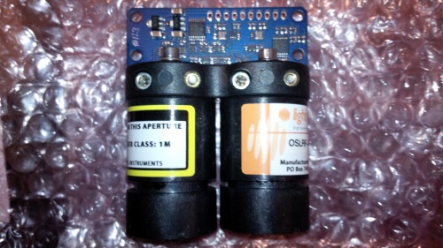
I was quite pleasantly surprised to see a package from DHL within just a few business days (Coming from South Africa to Canada!) and here begins my journey into un-packaging, marvelling, reading... more reading, whiteboarding, and developing a useful and cheap interface between this Laser Range Finder module, and our hobbyist Robots.
As the documentation describes, this is a bare bones Range finder, requiring a microcontroller to set up and process the ranging data. Nothing we are not all familiar with on our various IR and UltraSound Range Finders. There's just a little bit more to this one.
LightWare Optoelectronics employs Sequential Equivalent Time Sampling (a process developed by Tektronix to allow their oscilloscopes to work at higher frequencies) to represent a more manageable time scale for the Laser time of flight measurement. This allows us hobby roboticists to use our existing processors (Arduino or Atmel, PIC, Propeller, etc...) to interface and take measurements from it.
Directly from the manual:
The OSLRF-01 is a time-of-flight, “bare-metal” sensor that forms the front end of a laser rangefinder system. It runs autonomously
when power is applied and produces electrical signals that can be analysed to determine the time it takes for a laser pulse to travel
from the unit, to a surface and back again.
The OSLRF-01 solves the most critical engineering problems that designers face when making a time-of-flight laser rangefinder. These
are:
1. The laser needs to be “fired” using a very short current pulse of tens of amps. The high speed driver components must be
shielded to prevent optical and electronic leakage which would otherwise interfere with the detector and mask the return signal.
2. The detector needs to pick up the very weak return signal and amplify it to a level well above any background noise. This
amplification is done using high speed amplifiers that are expensive and consume a lot of power.
3. The time between the outgoing laser pulse and the return signal needs to be measured with very high precision in order to
calculate the distance. Clocking speeds of 15GHz would be needed in a timer capable of 1cm resolution and this is impractical.
4. Collimating optics for the outgoing laser beam and collection optics for the return signal are needed to make the system work
over a reasonable range. These can be expensive components.
The OSLRF-01 consists of a laser, photodiode, optics, amplifiers and sequential-equivalent-timebase-sampling (SETS) circuits. These
components work together to create signals that are easy to analyse, having been amplified and slowed down to a manageable
speed. The output signals from the OSLRF-01 include the outgoing laser pulse, the return signal and various timing references.
I am currently laying out a daughter card based on my exisiting I2C Atmel ATtiny84 Ultrasound Scanner. This daughter card will mount over the existing screw holes on the OSLRF01, will manage a pan servo, and provide 180 degrees of ranging data to your Robot or Autonomous Rover via I2C.
Future updates to this blog will document that process....
(Here is where you ask for features!)

References:
http://lightware.co.za/shop/en/laser-sensors/24-oslrf-01.html
http://www.google.ca/patents/US7746058
http://www.rp-photonics.com/time_of_flight_measurements.html
http://en.wikipedia.org/wiki/Time_of_flight
http://en.wikipedia.org/wiki/Laser_rangefinder