HX711 and a single strain gauge

Hi!

I require your help regarding a problem I’m encountering.

I am trying to use a single strain gauge (in a quarter wheatstone bridge formation) to an HX711 Load Cell Amplifier and an Arduino Uno. Am I able to connect the strain gauge to this amplifier and arduino instead of using a load cell? I was also considering using a Load Cell/ Wheatstone Amplifier Shield. I am better at hardware than software so the code for the arduino has also been stumping me.

Thank you so much in advance for your help!

Hello @mnev1155 and welcome to the forum!

Yes, you can use the strain gauge in a quarter Wheatstone bridge formation with the HX711. In the following image you can see a sketch of the connection.

Load cells are actually based on the same principle, they use different configurations of Wheatstone bridges with strain gauges and the HX711 module only amplifies and discretizes the difference of potential generated in the bridge caused by the mechanical deformation, you can find more information about this here.

Because you said you are struggling with the code I suggest you take a look at the Arduino examples available, you can find them here along with a very nice tutorial.

I hope that answers your question, let us know if you have any other doubts :grin:

Thank you so much for your response!

I had the set up that you drew but was unable to get any readout using the example code. Do you have any ideas for trouble shooting?

When I deform the strain gauge using the calibration code, there is no change in the reading. I have the set up exactly as depicted in the above image and am unsure about what could be wrong. Could there be in the circuit board somewhere or is it something wrong with the code?

Hello again @mnev1155

Could you share pictures of the setup? It would be useful to know more about the components you are using, like the resistors used for the bridge configuration, the electrical information of the strain gauge you have, an image of the HX711 module would also be great because there are many breakout boards with different pinouts.

There are lots of things that could be wrong, either on the hardware or the software. I’m guessing you already did, but make sure everything is properly connected by measuring continuity. Also, check if the bridge configuration you designed makes sense and if the pins in the example codes match the ones you are using. If you have a load cell or a similar device that needs amplification you could test it with the same example codes and that way you would know for sure the issue is with the Wheatstone bridge.

Hello again @geraldinebc15 !

Thank you for working with me on this!

Below are the links to the parts I have purchased:

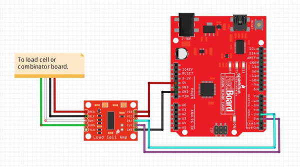
Also, here are some images of my set up:

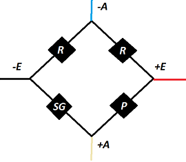
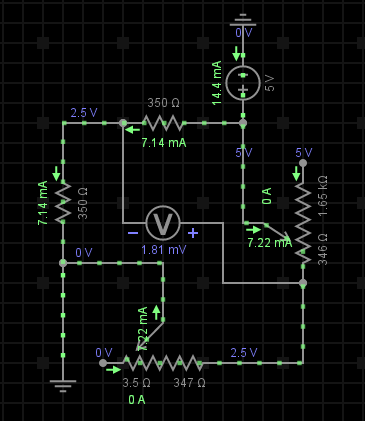
The 2K Ohm trimmable potentiometer is so that the output between the green and white wires in the wheatstone bridge is zeroed before any deformation has occurred. In wiring the circuit, I am able to measure the voltage across the ports and get it down to zero volts since the strain gauge does have a minimal strain on it initially in how it was applied to the surface.


If the pins for the ports specified in the code below are incorrect in the images, I accounted for that in the code or the placement of the pins.

I have been using examples for the HX711 Arudino Library. For example:

#include "HX711.h"

// HX711 circuit wiring
const int LOADCELL_DOUT_PIN = 2;
const int LOADCELL_SCK_PIN = 3;

HX711 scale;

void setup() {
  Serial.begin(57600);
  scale.begin(LOADCELL_DOUT_PIN, LOADCELL_SCK_PIN);
}

void loop() {

  if (scale.is_ready()) {
long reading = scale.read();
Serial.print("HX711 reading: ");
Serial.println(reading);
  } else {
Serial.println("HX711 not found.");
  }

  delay(1000);
  
}

I also tried the examples from the page for the Load Cell Amplifier Breakout Hookup Guide you had linked last time.

For some trouble-shooting, I have tested the continuity in the circuit. I have also soldered a new HX711 board together in thinking I might’ve fried the previous one. Also, I have extra strain gauges and I tried putting a strain gauge not yet adhered to any surface in the circuit and deforming it and was still not finding any output. However, when I deform the strain gauge and measure change in resistance with a multimeter, I am seeing a change. I have also tried changing the ports from the digital ones to the analog pins and accounting for that in the code.

From my understanding, the wheatstone bridge with strain gauge and resistors seems to be wired correctly. I am assuming that the issue is in how it is communicating with the Arduino and the amplifier. If you have any other suggestions for hardware to use to find the strain/load, I am open to using that as well.

Thank you in advance for you help! Let me know if I can make my thoughts/set up clearer!

Hi @mnev1155

If I understood correctly this is the wiring you have

image

I couldn’t really see the connections close to the potentiometer but I’m gonna guess you did it properly haha.
I simulated the circuit and this is what you have (1.8mV was as close as I could get to zero on the simulation but it is just an example)

image

Everything seems ok on that side but on the connections on the other side of the amplifier I noticed that the DAT (blue) and CLK (brown) connections are inverted on the Arduino

image

So you should either switch those or change the corresponding pins in the code. This is how it was originally in that example

#define DOUT 3
#define CLK 2

You mentioned you accounted for that in the code but I thought I should mention it since it is the only thing I see that could be causing problems. If you measured continuity and the connections are ok, you tested the strain gauge and is working and you are using the example codes with the appropriate pin connections in the Arduino the only thing I can think of that could not be working is the amp board, have you tested it with an actual load cell or some other component that produces a small signal so you can amplify that? Also make sure you set the same baudrate of the example you are using because I see the examples use different ones.

Thank you again for working with me on this!

So I attached a 4-wire load cell that I had and was still not getting any read out.

In checking for continuity and making sure that the amplifier board is working properly, what should I be testing specifically on the board? I cannot tell if the green/white pins should be giving me a signal when using the multimeter to verify continuity. Where are points that should be checked on the board to make sure that it is working properly?

Thank you!

I’m sure you already did it but you should measure continuity between the connections on the breadboard and the breakout board and from the breakout board to the Arduino.

If you want to test for shorts in the breakout board you can try this guide, it is ok if you can’t make all those tests but at least you can measure the resistance between neighbor pins which shouldn’t be too low (it is not recommended to test that with continuity feature on the multimeter because it injects current between the pins).

Hello again!

There was one day that I was able to get out on the ardunio using the breadboard. I also shorted the VDD and VCC as it says to do so in the schematic. Then I transferred it all over to a protoboard and now no readout again. I am also getting messages on my computer saying that there was a power surge in the USB port. The wheatstone bridge circuit seems to be working correctly when I check the resistances and voltages across each resistor. Could I be frying my HX711 somehow that it won’t talk to the computer anymore?

Thank you!

Hi @mnev1155, sorry for the delay

The problem you are experiencing is a bit strange and I’m afraid I won’t be able to identify what is causing it from distance :pensive:

From what I understood there was a time when you made the HX711 work, I suggest you go back to that stage and start again carefully, checking all the connections. The surge in the USB port message is a bit troubling and you should pay attention to that since it could mean there is a problem either in your port or on the Arduino board. Also, to make sure there is nothing wrong with the Arduino you could try testing another sensor if possible or at least run an example sketch like the “blinking led” one.

I’m sorry I can’t provide further assistance but I’m sure you’ll be able to figure something out :wink:

Thank you so much for your assistance!

It turns out that the sensitivity of the potentiometer was severely hindering the arduino’s ability to read any change in resistance. I just had to dial it in a little bit better to be able to see the change.

1 Like

Hi again!

I’m glad you were able to solve the issue :partying_face:

Thank you!

If I’m getting a lot of noise in my output, could I add a low pass filter? If so, where would it go in the circuit? Or is there alternate hardware that would smooth my output?

Hi @mnev1155

There are many ways to reduce noise, you can find some of them listed on this website: http://www.microlink.co.uk/signal-noise.html

Summary of Reducing Noise: 6 Tips

  1. Keep the signal wires short
  2. Keep the wires away from electrical machinery
  3. Use twisted together wires
  4. Use differential inputs to remove noise common the both wires
  5. Use an integrating A-D converter to reduce mains frequency interference
  6. Filter the signal

As you can see some of the methods used for reducing noise include using differential inputs and using an AD converter to reduce mains frequency noise, by using the HX711 Load Cell Amplifier you are already doing this. You could also add a low pass/anti-aliasing filter to reduce noise error, but you would have to design it according to the characteristics of your circuit.

The cut-off frequency must be compatible with the frequencies present in the actual signal (as opposed to possible contamination by noise) and the sampling rate used for the A-D conversion.

Here you will find some information about LP filters and here about anti-aliasing filters. You would have to add this circuit between the bridge and the HX711 but by doing that you will probably unbalance the bridge, that is why it is better using an instrumentational amplifier (differential inputs) because the high resistance in the Opamp inputs avoids unbalancing the bridge.

Another solution would be adding a digital median or average filter, which is pretty simple. You would only have to take M samples of the output signal at a time and take the median or average of those to produce a single output point.

hi

I am facing the same problem, can you plz share me what changes you did in circuit

Hi so I am going to be running a very similar circuit with a half stone and diagonal stone bridge. Every example code I find is for a loadcell, is there anything in the general codes for load cells that must be changed for the strain gauges, like unit stuff? Also does the code output the readings in mV? and if so how do i convert the mV reading to strain?

I think your problem is in the potentiometer. It is very difficult to tune it to the correct place. If you read the datasheet of HX711 you will find that under the 128 gain, the input variation is ± 20 mV. It is very difficult to manually tune the potentiometer to zero it out. That’s probably why people prefer using a load cell that has the strain gauge and accurate resistors inside.