It took so much time to get this working. But know everything works fine. Using RSSI you can make many funny projects, like object detection and so on. Check out the link below for more information about RSSI.
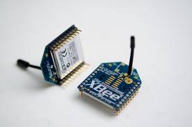
XBee modules have an RSSI (Received Signal Strength Indicator) pin that outputs a PWM signal representing this value. But how do you turn that PWM duty cycle into a useable integer on your microcontroller? Luckily Arduino has a function made for just this application:pulseIn.
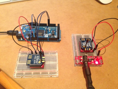
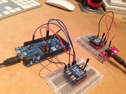
Connect the RSSI pin (pin 6) to a digital pin on your microcontroller.
Use this line of code in your Arduino loop:
rssiDur = pulseIn(digitalPin, LOW, 200);
pulseIn returns the duration of a pulse (specified HIGH or LOW) in microseconds (µs). The 200 is a timeout value in µs—it waits this long to see if there’s going to be a pulse. Since the XBee’s RSSI PWM period is 200µs, we want to wait at most that long to see if there’s a pulse at all.
Since this function gives you a duration, it’s up to you to map that to a value relevant to your program. Since the maximum duration of the pulse would be 200µs, you could map that to your logical maximum.
Keep in mind that if you were planning on using API Mode anyway, every API Mode packet has the latest RSSI within it.
I am using an Arduino Due and IDE 1.5.4 with two xbee pro series 2. The router in AT mode you set Digital pin 3 as A/D config which is physical pin 17. What is this pin used for? I didn’t see anything connected to pin 17 in your tutorial? I have configured the two xbees as per your tutorial but I had to wire the xbee tx to the arduino rx (Serial3) and visa versa, to get a readout on my serial monitor. Could you please explain why you connedted tx to tx and rx to rx? The serial monitor only displays zoros and no RSSI values. The led on pin 13 stays on even if I swap the HIGH and LOW in the code? Do you know why any of this is happening?
I am trying to build a unlock/lock remote for my car triggered at a certain distance.
First of all, its very difficult for me to solve your problem because i need your setup information. Show me a picture of your hardwaresetup, so I can have a look.
The router Xbee has to get data. This means you have to set A/D number 3 to enabled and set the sampling rate. You dont have to connect any wire to this pin 17, because it works with dummydata too (It works even if pin 3 of your xbee reads zero). Actually I dont know why I connected them TX TX, but it worked for me. If you only get zeros try my arduino sketch and change the setup afterwards, so you can make sure everything is set up correctly. So first use my sketch!
Router xbee in AT mode with digital pin 3 set to A/DC and power to it.
Coordinator xbee in API mode with power to it, tx to Arduino rx and rx to Arduino tx. PWM pin 6 on xbee to digital pin 10 on Arduino Due.
I have been using your code with this setup but I still just get zeros on the serial monitor and the led on pin 13 stays on. I can't figure out why I am not readiong the rssi? I hope the pics are clear enough for you.
Did you set the sampling rate of the Xbee AT Router Digital Pin 3? This is very important! (Watch my video and do it like i did). I sometimes got zeros when the connection between the two Xbees did’t work. Check the network ID too.
Everything you did in the tutorial I did to the xbees in X-CTU step by step. My pan ID’s are the same the my high and low destination addresses are correct. Would a reset and re-configure of each xbee do anything? I can see the TX on the serial port (to the computer) flashing with data on the Arduino Due, as the zeros appear on the serial monitor. If I hold the xbees in the setup right next to each other the zeros stop scrolling and then when I separate them, the zeros start scrolling again? Also I know the xbees are communicating because in X-CTU it will not let me read the coordinator because there is data coming in and you can see it in the terminal. Does the fact that I am using an Arduino Due with IDE 1.5.4 change anything?
I went out and got an Arduino Mega to try to get your rssi set up working and I am encountering the same problem - I am still getting zeros. As shown in the photos I posted a while ago, I have the same set up but with an Arduino Mega and using IDE1.0.5. I even tried to get it working on a pc instead of my mac with no results. I am using your exact sketch and followed your xbee configuration in XCTU exactly. I know the xbees are communicating. The TX light is flashing and the LED is on. In your tutorial near the end were you show the rssi numbers in ther serial monitor, you say “I’ve set it to debugging in my sketch”. What dest that mean?
Is there any other configurations I need to do to the xbees or settings I can change to get the rssi value to work?