Hi guys.
I am working on my ISD4002 chip and i am now going through the recording part. This is what the manual says:
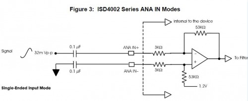
"[...] a 32 mVp-p (peak-to-peak) maximum signal should be capacitatively connected to this pin for optimal sound quality"
My question is: how can i be sure the right amount of voltage is gonna enter that ANA IN+ pin? I am also not sure how to measure the source voltage (coming from the "line out" hole from my computer).
Hi,I have found a swedish
Hi,
I have found a swedish website. In the schematic a simple potentiometer have been used on ANA IN+. A higher voltage will only result in a distortion of the output signal, it will not kill the chip. I am not shure about the lineout voltage from a soundcard, but I think it can reach 2Vpp.
Hope this will help you.
thanks mate, but i also had
thanks mate, but i also had found that site before 
But how can he know that with a 4.7K resistor he will limit without knowing the aumount of current he wants to flow in? What i mean is… i could find out the correct resistor if i also knew the current needed, but without that i don’t know how to get to it.
I am gonna use the 4.7K resistor, but if i don’t find out why i won’t sleep peacefully tonight :D…this happens with every project of mine actually
BTW, what’s that symbol in
BTW, what’s that symbol in the second schematic (the second one in the hardware section) that shows the 4.7K resistor with an arrow pointed to it?
EDIT: sorry, i got it. It was one of my dumb moments


