How to connect SRF05 to Picaxe 28 pin Project board

If you are a newbee, you may only have learned that the Picaxe 28 pin Project Board has some inputs and outputs.. And you may have purchesed an SRF05 (that Picaxe refers to as SRF005), and you are trying to connect the darn thing.. without resoult?

Reason is likely to be that you are connecting the output from the Picaxe to the SRF05 through the darlington on the board.

The SRF05 needs (like many other things) a Pulse-signal, not just a "power on / off". The signal therefore must come directly from the Picaxe chip.

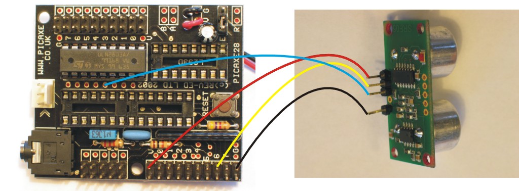
Luckely the board has little "hidden" holes for that kind of conections. (Blue wire, the signal in to the SRF05 directly from the chip). These holes, however, are not described, simply omitted in the manual for the board. So I wonder how a newbee should ever find out, personaly I burned a SRF05 or two in my frustrated attempts to get it right :)

If you follow the illustration above, you should be able to make the below code work just fine. You will know that the SRF05 is getting a pulse-signal when the little red LED on it´s back is flashing red.

****

symbol trig = 3 ‘ Define output pin for Trigger pulse
symbol echo = 6 ‘ Define input pin for Echo pulse
symbol range = w1 ‘ 16 bit word variable for range

main:
pulsout trig,2 ‘ produce 20uS trigger pulse (must be minimum of 10uS)
pulsin echo,1,range ‘ measures the range in 10uS steps
pause 10 ‘ recharge period after ranging completes
‘ now convert range to cm (divide by 5.8) or inches (divide by 14.8)
‘ as picaxe cannot use 5.8, multiply by 10 then divide by 58 instead
let range = range * 10 / 58 ‘ multiply by 10 then divide by 58
debug range ‘ display range via debug command
goto main ‘ and around forever

****

Notes:

I did not have a fresh SRF05, and so there are drilled extra holes and soldered pins on the one on the picture.

Be aware that if you also connect servo(s) to the same Picaxe chip, program execution may be bumpy with little iregular breaks when using things as the SFR05 that needs pulses. If it is important for you to have a steady program execution, or if a servo acts totally irrational, it sometimes helps to have a smal pause or turn off a servos pulse for a short time in the code:

"low 3" or "pause 10". Aparently there is no system, it is just trial and error with your particular setup.


These pages might have your interest: See what Robot Sees, 28 pin Project Board (AXE020), Picaxe for dummies


Tak
Nice guide, havn’t got my Picaxe yet, hope to get it today

:slight_smile: Looking forward to seeing

:slight_smile: Looking forward to seeing your first robot or creation in here in some time soon then :slight_smile:

/ Frits

Bought the Wrong Sensor…

Hey Dude,

It seems I bought an Ultrasonic Sensor (Parallax #28015) and it is one for a stamp not a picaxe…

Any thoughts?

I’ll check back here, but you can also zap me back at

[email protected]

or

[email protected]

Thanks!

www.rocketbrandcustom.com baby!!

Dude!

Well… the parts will work together, for sure.

The one you have is somewhat simpler, it uses same pin for in and out.

Good news is that the smallest Picaxe, 08, also only has this available, and so the folks at Picaxe have prepared the SRF005-manual for a special mode: Special Mode 2 - For use with PICAXE-08/08M microcontroller.

Look in this file:

http://www.rev-ed.co.uk/docs/srf005.pdf

You will however have to play around and read some (easy) documentation regarding which pins you should use on the particular Picaxe you have. I presume it is an 28X1? You should find a pin on it and use it for both in and out. The pin should be directly connected to the leg on the Picaxe - not through a Darlington or motor driver or anythiong else.

you should also check the documentation on your sensor

http://parallax.com/Portals/0/Downloads/docs/prod/acc/28015-PING-v1.5.pdf

and try to understand the pulses, and translate the timing to Picaxe-basic.

To put it shorter:

I would adapt the SRF005-Picaxe-08-part of the code with the pulse-etc-times in the manual for the Ping.


You can subcribe to posts on this website so you wont have to check in when there is an answer, and wont have to flaunt your mail adress :wink:


/ Frits

Is there an easier

Is there an easier reccomended way to connect them, than to connect each and every single wire through solder?


Can anyone post acutal pictures of theres?

http://letsmakerobots.com/nod
https://www.robotshop.com/letsmakerobots/node/719

Ok, so what am I supposed to
Ok, so what am I supposed to do, I find connecting every pin to each wire tedious and its a nucense because i still have some solder leftover on the board and I am afraid of the board breaking


What am I supposed to do?

What am I supposed to do? There are perhaps 1.000 members in here. If everyone was asking how to connect every wire!?!

Stop whining, and try to build a robot, you know :slight_smile:

(yes, I am drunk)

*1,000 not 1.000 *
1,000
not 1.000


:smiley:
:smiley:

hellloooo
hello i have this microcontroller ive made a topic thing on this site witch i LOVE btw note why love is in capitals haha lots of info very good although im a newbie plz look at my topic thing ty =]

Does anybody know how to
Does anybody know how to make a simple mount to hold the SRF005 and attach it to the servo?? I sort of forgot about that bit till it was to late…

Cascabots
Check out here : http://cascabots.com/index.php?act=viewCat&catId=1

I’m still awaiting my
I’m still awaiting my package btw… idk if thats such a reliable site


jumpers
Solder header pins into the sensor and then one into the project board (where the blue one goes). Then you can just use four jumpers. That way, you only have to solder once. I learned this the hard way after f$*%ing up my project board …

same here, hope it arrives

casca’s? I complained to
casca’s? I complained to Paypal…


im going to be starting a

im going to be starting a robot soon and i wanted to use the ultrasonic rangefinder over the infared one, thanks for the post!


if everyone were worms, try to be a glow worm

annoying
Why in the hell does it need a pulsin of at least 10uS ???