Hello, I recently purchased the Firgelli L12 series linear actuator L12-100-210-21-1 from RobotShop.
I would like to change the rod end from the default (clevis) to the other rod end (threaded 10-24). The manual says to “When changing rod ends, extend actuator completely and hold the round shaft while unscrewing the rod end plug”.
My question is does the actuator need to be powered in order to do this? I attempted to pull the actuator a little bit manually but I didn’t want to damage it so I didn’t use a lot of force. I did not yet purchase the linear actuator control board. Can I just provide a simple power source to one of the wires in order to extend the actuator to change the rod end?
Many thanks,
Johnny5
Thank you Coleman, I am planning to use the 0-5V interface for now.
Cbenson,
I tried the wiring setup that you described. Whenever I adjust the output voltage of the controller, I feel the actuator vibrate, but it does not extend. It seems like it is trying, but something is stopping it. I tried with a higher amperage power supply (1A) and I got the same result. It seems like the wiring is correct but it is unable to extend. Any ideas?
Thank you.
Johnny5
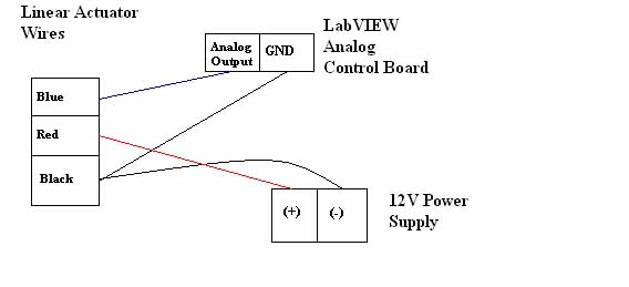
This is how I wired the actuator:
Isn’t lead 1 the green wire (4-20mA) according to the manual? Perhaps it is a typo? It says the set point voltage must be held on lead 1, whereas lead 2 is clearly indicated as the 0-5V input. The formula makes sense to me. So if I want the stroke position to be 50mm and the full stroke length is 100mm, then I input 2.5V. I will power everything off and keep trying with the lower amperage power supply to be safe, and I’ll check the voltage using a multimeter. Another potential issue is I might have had the 2 wires from the power supply backwards. Those wires aren’t color-coded.
I spoke with tech support at Firgelli and they said reversing the polarity would have no effect and would not damage the actuator. Anyway, today I used a multimeter and confirmed the correct polarity of the 12V power supply and also confirmed 2V being sent to the actuator from the controller on the blue wire and on the lead itself (to confirm the wire was secure), and the actuator still hasn’t budged. I don’t know for sure but it seems like it might be a defective part. Could I exchange it for a replacement? It’s robotshop.com/productinfo.aspx?pc=RB-Fir-38&lang=en-US
Thanks,
Johnny5
Thanks Cbenson. I submitted a ticket to them and they responded EXTREMELY fast and made everything very easy. Seriously, I am blown away by the great customer service here. Not to mention you replying to my thread like every single day. Awesome experience overall!
As for the R/C signal: for the LabVIEW module, I assume that would be a digital output, and I don’t know how to do that per se. I will give it a shot nonetheless and let you know the result. Perhaps the 0-5V interface mode was just defective.
Best regards,
Johnny5
You should only be changing the black insert at the end of the rod - not the entire rod itself. You cannot pull the actuator because the mechanics use a lead screw design (self locking). Option I does not have a simple 2 wire control method.
The -I version is the best choice because it accepts so many different communication methods. There are two groups of wires; one is for R/C or PWM, the others are mostly for Analog. In your case if you want to use an analog pin, we’d suggest starting with an R/C interface (white/red/black wires); you’d connect the red wire to 12V, the black wire to GND of the battery and of the controller, and the white wire to an output pin capable of producing a 1250us to 1750us pulse, repeated every 20ms. Another option is of course the 0-5V interface; red and black wires are the same as before, and the blue wire goes to an analog pin which produces a 0-5V signal which corresponds the the position. Refer to the guide for more details.
Wiring looks fine. Need to refer back to the L12 datasheet, page 3: 0-5V interface mode.
“The desired actuator position (set point) is input to the actuator on lead 2 (blue) as a voltage between ground and 5 V. The linear relationship between the input voltage and the actuator position is determined by the formula I = 5P ÷ S, where I is the input voltage (V), P is the desired actuator stroke position (mm) and S is the full stroke length of the actuator model (mm). The set point voltage must be held on lead 1 until the desired actuator stroke position is reached. Lead 2 is a high impedance input.”
As always, if it does not work within a second, power it off to try to ensure nothing burns. Double check the voltage is what you set it to be using a multimeter.
That can potentially fry the electronics…
For exchanges / returns - please contact the Exchanges/Returns dept in the RobotShop Support Center. Be sure to provide your invoice or order number.
Can you send an R/C pulse of 1500us repeated every 20ms from your microcontroller? This would help you see if R/C mode works.


