

Some time ago I have announced my remotely (over the Internet) controlled robot. However, there were not too much documentation and details. So with this post I would like to announce the availability of more detailed project documentation and make brief overview of some interesting aspects of the project. The whole available documentation could be found on the project Wiki. It is, as usual, :) not complete yet, but hopefuly good enough to understand how everything works and even rebuild it yourself.
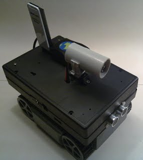
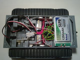
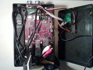
Here is the brief summary (details are available here) of what we have done so far. As a chassis platform we are using the one from Pololu. On top of it we mount the BeagleBoard with connected WiFi adapter, camera and GPS receiver. To control the motors we are using standard PWM-controlled speed regulators. Control PWMs are generated directly from BeagleBoard using available hardware PWM generators as well as using GPIO. In addition, there are compas and ultrasound range finder connected over I2C available on BeagleBoard.
Here is how it everything looks like now:
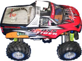
Or like this, depending on what chassis are used:
Video is compressed in to h264 stream using OMAP's DSP in real-time. TI's DSP optimized codecs integrated with GStreamer are used for video compression. After that, the h264 stream is sent to the driver console over WiFi. We also solved a lot of problems related to firewall and NAT traversing.
Experimentally we found out that maintaing constant video frame rate is the very important to provide comfortable driving experience. It is not a trivial goal to achiev if the video is transmited over the Internet because available bandwidth changes permanently. To solve this problem we developed our own adaptive video streaming infrastructure. We have presented our adaptive streaming on the Gstreamer 2010 conference. There is presentation video and slides available.
In addition to the video stream, driver console also receives data collected from on-board sensors. It makes it possible, for example, to display robots current location on the map which is downloaded from the openstreetmap.org also in real-time.
The following picture illustrates how the driver "cockpit" looks like:
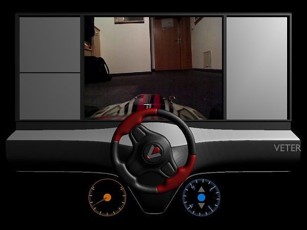
This is real screenshot (not a photoshop :-) ). Driver console application is written using OpenGL and works on Linux and Windows (should also work on Mac but I did not test it). The whole 3D model is made in Blender and exported in to the standard .DAE (COLLADA) format. So the project also contains rather evolved COLLADA visualisation library which supports animation and some other advanced features. Every time the new video frame is received and decoded to the raw RGB data block, the corresponding OpenGL texture is updated in 3D scene. The middle panel is then used as such textured surface. Panels to the left and right are to visualize additional information such as for example map with current location or to constantly scroll unreadable cool looking logs :-) .
I want to say special thanks to Sungreen (aka. Nikolay :-) )! He is kindly respond to my call for help on blender-3d.ru site and created different 3D cockpit models. If you are interested, you can take alook at this link. The site is in Russian but on the 2-nd page there are several examples of the alternative cockpit models.
All the software for this project (including recepies for OpenEmbedded/Angstrom to build Linux image for flash card) are available on github.com. We are currently in process of migrating from gitorious.org to github, so if some pieces are missing on github, chances are that they could be found in old repository.
Also, for some additional information about the project I would suggest to check our Blog.
I would really appreciate any comments about the project!