How would you make a pivot that would allow motion in an arc around a tube of a larger diameter by a tube of a smaller diameter? The pivot must be able to be moved along the larger tube for adjustment.
Some starting ideas:
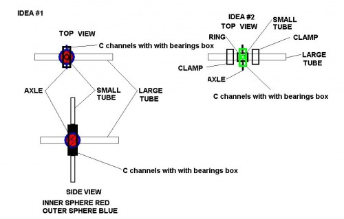
Nested hollow spheres. The inner sphere is split and drilled to fit around the larger conduit. It is held together by recessed cap screws. The outer sphere is drilled and hollow so that it can pivot around the large tube. Perpendicular to the hole there are two pivot axles. Mounted on the axles are two C channels with with bearings which form a box around both spheres. The second smaller tube is attached to the non-bearing sides of the channel-box. -[o]-
Replace the spheres with a ring captured by two clamps which are tightly around the larger tube and enough room between the clamps to permit the ring to pivot around the large tube. The ring has two pivot axles. The remainder of the pivot is similar to idea #1 above.
I’m having trouble visualizing what you need, even with your diagrams. So I’ll ask some questions.
How strong does this need to be; how much weight does it need to support?
Does this two-axis tilt have just two degrees of freedom? 1) smaller axis pivots around larger axis, and 2) smaller axis slides along length of larger axis?
Is there a commerically available pivot unit you can provide a link to as an example of what you need?
Could you upload higher resolution images to an external image hosting site (Flicker, Picasa, etc.) and provide a link to them? It is hard to see the detail in your diagrams.
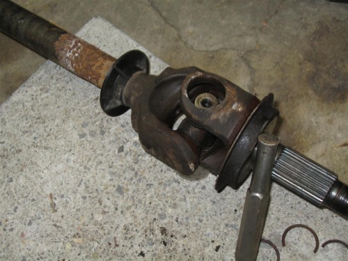
A U-joint transmits torque. We need to transmit motion on two axis. One along the axis of the large tube. The second perpendicular to the axis of the large tube. Plus, we need to be able to adjust the point at which the joint crosses the tube without damaging the tube.
Thinking,
thinking,
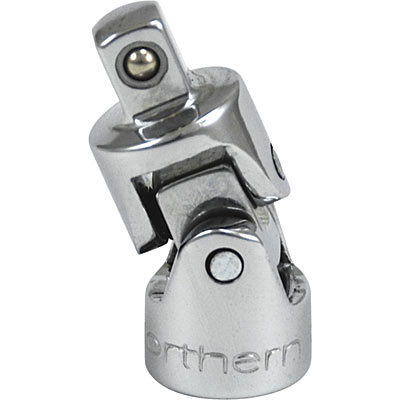
ahh: If the large tube was the lower pivot in the image of the joint above, and the center block was able to slide along the tube, and move the lower pivot to the center of the upper pivot so that they cross like the automotive universal, drop the bottom part of the wrench-universal entirely, and the top wrench-universal part's ears extended past the pivot to the other side of the lower pivot, then you would have what is needed.
The large tube is 35mm steel, the small one 25mm aluminum
how much weight does it need to support?
~10kg
Does this two-axis tilt have just two degrees of freedom?
I'm not sure what that means. The idea is that the smaller tube pivots around the larger tube, about 120 degrees in two directions.
1) smaller axis pivots around larger axis, and 2) smaller axis slides along length of larger axis?
I don't understand what a smaller axis is, sorry.
Is there a commerically available pivot unit you can provide a link to as an example of what you need?
Not that I have found
Could you upload higher resolution images to an external image hosting site (Flicker, Picasa, etc.) and provide a link to them? It is hard to see the detail in your diagrams.
OK. That description at the end of your message makes my brain hurt.
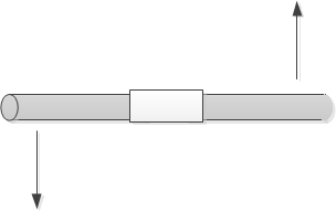
Let me try this set of descriptions, and let me know if I’m right or wrong. In my statements below, ‘spin’ means rotate around the center line of the axis, like an fixed axis holding a wheel would spin.
'Rotate' means the axis turns end over end around the center point.
'Move' means the two end points of the axis are moved relative to each other, but not in the direction allowed by the pivot. So this motion will cause the pivot point itself to move or rotate.
OK, now for the descriptive statements.
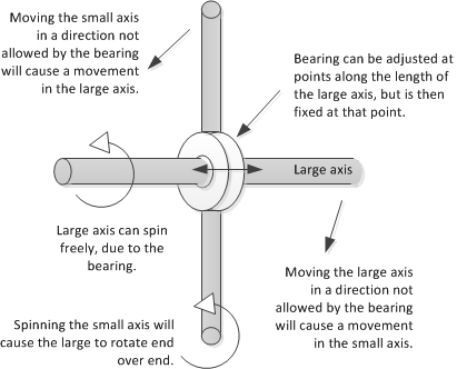
You have a large axis, with a smaller perpendicular axis that is bisected by the larger.
The smaller axis can pivot 360 degrees freely around the larger axis.
The small axis can be fixed to a point along the length of the large axis.
The small axis can also be adjusted and slid to a different position along the length of the large axis.
The large axis is free to spin without affecting the small axis.
If the large axis moves (the two end points are moved relative to each other), it will cause the small axis to shift.
The small axis cannot spin freely, because it is fixed to either side of the joint. Spinning the small access will cause the large axis to rotate.
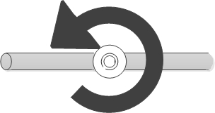
If I put all this together, it looks something like this:
If my drawing and description above is accurate, you could build this as follows.
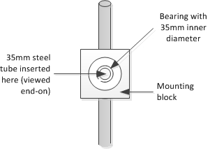
Buy a bearing with an inner diameter to fit your 35mm steel tube. The steel tube slides inside your bearing. You can use two collars to fix the position of the bearing along the length of the steel tube.
Create a mounting block of wood/metal/plastic/whatever, and drill out a hole that will pressure fit the outer diameter of your bearing.
Your aluminum tube is mounted to either side of the mounting block. Depending on the wall thickness of your tube, you may be able to thread it with a tap and die set.
Response to ignoblegnome "You have a large axis, with a smaller perpendicular axis that is bisected by the larger." YES
“The smaller axis can pivot 360 degrees freely around the larger axis.” yes but 120 degrees
“The small axis can be fixed to a point along the length of the large axis.” YES
“The small axis can also be adjusted and slid to a different position along the length of the large axis.” YES
“The large axis is free to spin without affecting the small axis.” In the real world the large axis is not going to move but in this discussion it could spin 120 degrees
“If the large axis moves (the two end points are moved relative to each other), it will cause the small axis to shift.” YES (I think)
“The small axis cannot spin freely, because it is fixed to either side of the joint. Spinning the small access will cause the large axis to rotate.” YES
However, the drawing does not show the tilting of the small axis along the length of the large one.
Here is something that moves like what I need. A joystick. It can be pushed forward and pulled back. It can be tilted from side to side. Now, imagine that it is mounted on a horizontal pole and the joystick handle has another handle on the opposite side of the pole that moves in the other direction of the one on top. Tilt the stick along the axis of the pole and the bottom stick tilts towards you. Tilt the stick towards you and the bottom tilts away. Tilt it to the right and the bottom tilts left and so forth.
Now, imagine that this entire assembly can be slid along the pole and locked in a new position.
required to be in the same plane as the large axis? Could you instead offset the smaller axis to one side of the larger axis? If so, you could put a movable ball joint on the large axis and then connect the small axis to a pair of rings that could capture the ball.
Response to birdmun Thank you for the comment. When I read your suggestion, “Could you instead offset the smaller axis to one side of the larger axis? If so, you could put a movable ball joint on the large axis and then connect the small axis to a pair of rings that could capture the ball.” I imagined a ball on a shaft connected to the side of the large axis with a socket holding the small axis. The small axis would have to be bent around the large so that it ended up by being centered on the large axis. This would work. The difficulty is finding or making the parts.
However, this is not what you were suggesting. Your suggestion is similar to my first idea. You replaced the larger slotted ball with the two rings. This too would work.
However, I don’t see how the rings are held together or to the small axis. Did you have something in mind to accomplish these tasks?
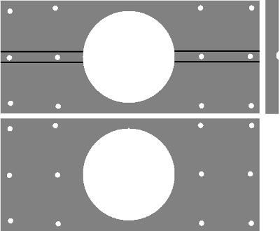
could be accomplished by drilling 4 equadistant holes and running bolts through then adding a nut to the other side. As for the small axis, JB Weld comes to mind or epoxy of some nature.
Good idea. And the small tube could be attached with two rods. Each rod has two flats to fit between the rings and with a hole for one of the bolts. The tube could slip over the rod and be bolted to the rod as well as the rod bolted to the rings. Very nice idea.


