First, let me thank the Forum Community for the help to get my Phoenix 3DOF Hexapod project off the ground! It is a spectacular Bot! A special thank you goes out to @scharette . I also want to share some of my experience with others to assist with filling in some build instruction gaps and help avoiding pitfalls during their project build. I just need to know how and where to post this information (already written up but can’t figure out how to post).
Now My Ask: I have figured out all of the PS2 Button/Function Controls (a special thanks goes out to the Genius who wrote the code) but I come up with a blank on GP Player Sequences. Apparently, the Arduino Sketch leaves this blank for User content? And, I cannot find anything regarding how to add a GP Player Sequence to my Bot on the Forum or any other information regarding this on an Internet search (only that it is an option). I have seen a video, using a RC-type controller which has a GP Player sequence that lifts only the 2 front legs while crouching backward in a classic arachnid attack pose which I would love to add (Crouching Phoenix - Hidden Code?) . Does anyone know how to accomplish this?
I have a standard RobotShop Phoenix Hexapod Build with Botboarduino and SSC-32U Servo Control PCB with PS2 V4 RF Control.
I’m sure that I can’t be the only Phoenix Hexapod Enthusiast with this particular desire and ask for your assistance here.
Thank you all in advance for any advice and help which would be greatly appreciated.
You may also want to contact the creator of the Phoenix code, @kurte. It has been years, but he may be up to answering some of your questions once you’ve done your reading!
We are certain too! That being said, it is an expensive robot to build so it is still a niche market, especially considering the large amount of options!
Hopefully the links above will help you get started with hunting down what the Phoenix code does with the GP Player.
Of course, I should mention you should check the old SSC-32 manual for the GP player. It is available here. Reading this should give you a good idea on what can be done with it and how and help understanding the code from the Phoenix.
Thank you for the quick and informative reply. I will try to decipher the appropriate code content per your identified lines with a printout and reach out to Kurte when I have intelligible questions. My code experience has been more adapting, altering parameters and then trial and error testing so this is a real challenge for me.
I also have created a revised PS2 Control Button Functionality Chart (the build documentation being the source of the chart) using “cleaner”, more succinct and minimized language with a couple footnotes regarding the definition of the Balance Mode (“Smooths out Walking Gait Motion {body tilting with leg motion is quieter}”) and that the “GP Player Mode default has no Sequences or Function Unless Programmed by User”. I’ve also removed the double lines and increased font size and bolded the key action/description words for better visual use. The Balance Mode is a very elegant enhancement and significantly reduces the Bot’s noise level especially on hard surfaces but I found no reference to this when doing searches. If it were up to me I would have called it “Stealth Mode” as this phrasing more aptly describes the impact/function of this Mode.
With the chart, I also created a PS2 Graphic Diagram with Button Functions Labeled to assist with initial use and exploratory use of Bot functions. Before posting, I’ll send you the file for your input (comments, suggestions, etc.). Just the exercise of creating this both assisted with my education of the Bot’s Functions and its extensive functionality. It will be in a PDF printable file which will allow a 2-sided printout to have the chart on one side and the diagram on the other as a Quick Reference Guide. I would appreciate a suggestion of where this should be posted in the Forum and how to make the appropriate announcement to the Phoenix community that this resource exists. Currently, I’m working out the bugs and reviewing for errors and omissions before I can send you a “Beta”. Please advise on how I send this document to you or make it viewable prior to posting.
I have 3 pages of build tips and suggestions and will add a couple more before posting. There is also no reference that the PS2 Rx works at 2.4GHz which has a very limited FCC power limit. Many of the Phoenix builds that I have seen posted have the PS2 Rx on the bottom of the Bot (under an aluminum frame???) or directly on top of the frame which greatly attenuates the range and reliability of the received signals. Stacking the Rx on top of the PCBs will optimize performance.
Great to see you getting a challenge that is motivating! That’s probably one of the best ways to learn.
Looking forward to seeing the doc you are creating. We can create a new topic in private (they can include multiple people) to discuss these things as needed. I’ll send a test private message later.
I assume you are working in a draft for those (robot, tutorial or blog)?
I figure this is the case because:
The robots need visual range, don’t have much mobility (no terrain adaptation) and therefore you don’t expect them to go very far. i.e.: the lower range / signal strenght does not matter if you are a few meters away (as far as I can see).
The very low data rate (the packets are super small, too) also make signal integrity and strength less of a problem.
probably not too important in this application (low data rate).
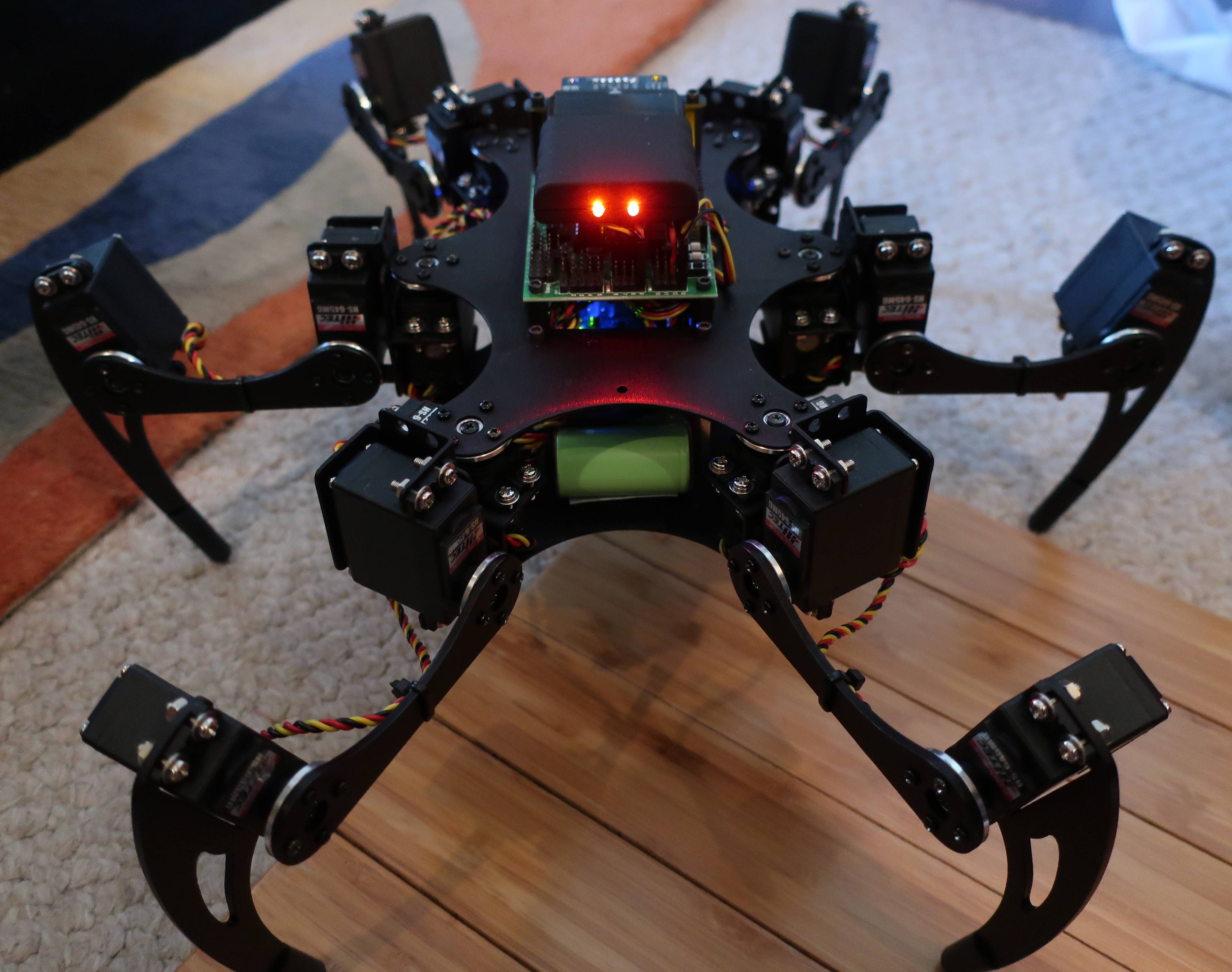
All valid input regarding PS2 Rx locations. Besides a “clean” undercarriage, there was another reason that I chose to locate the Rx on top. I really liked the 2 Red LED “beady eyes”) of the Rx which gives the Bot some ominous character. Unfortunately, my older PS2 Controller did not survive 6 years of storage (switch became unreliable and unrepairable) and I needed to replace it with the newer version with One Green LED (an undesirable Lopsided Cyclops look). With a little “surgery” I was able to replicate the 2 LED “Eyes” and actually use the old PCB shell enclosure of the removable module. The second solder pad is still active but the power is not the same as the 2 LEDs lumen output is too unbalanced so I just fed both through the main pad (Power ON/Signal pad) and it works fine. Utilizing the old shell took some PCB trimming but it’s better than drilling out new holes in the new enclosure to achieve the desired results (please see picture attached). The one other benefit of the new version of the Rx Module are the 2 mounting holes on the PCB which align with The holes on the chassis and PCBs.
Also, with a little surgery I was able to relocate the 90 degree standoffs of the Rx board relocating them below the PCB with the pins pointed in rather than out, allowing the leads to then “fold” under the Rx Module making for a much more tidy appearance and overall smaller footprint (please see pictures attached). This is not difficult to do and could also be appreciated by those whom have located their Rx Modules flat to the top or bottom chassis plate.!
I learned that removing the 6-Pin Header was easier if the header pins were first straightened out, the black plastic pin retainer/separator removed and then each individual pin could be more easily removed when individually heated and removed with needle nose pliers (however, this means that you need to have a replacement 90 degree header handy). Soldering wick was not effective for clearing the holes on the PCB so I tried heating the solder and using a compressed air can (straw nozzle at the hole). This is my new go-to hole clearing/de-soldering method! Works beautifully.
I really love that too. When I was testing the hexapods I would place the BotBoarduino inside the frame but use long cables to connect it to the PS2 receiver, which I would place with double sided tape at the front completely. This would give it that ominous look you mention and act like a “head”. Maybe I should added a small 9g servo to it to make it move, too… or even a small pan & tilt!
Wow, that is dedication… ! I figure you could’ve also just connected the two LEDs in parallel with a resistor in series to the 5 V / GND rail of the receiver.
That look makes me think of the boss monsters in the old Sonic games on Sega Genesis!
I appreciate the observations. Since the Rx Module Housing is part of the build (had to be there), was black and already had power I decided not to reinvent the wheel. Oh, and let’s call it like it is, that was “obsession” and not “dedication”… You were being too polite.
However, when looking for an alternative before going through all this trouble (with the risk of causing more damage than good), I went through the BotBoarduino manual and did find the 5VDC Pin as well and adjacent 3VDC Pin which would not require a resistor and tested it with a LED. I actually have a plan to add an optional and removable plastic dome (1/2 of an arts and crafts sphere painted black and possibly with furry material. This would also have 2 eyes and also incorporate an audio module (record playback type ~$6) with a hole for sound in the dome (masked by material). Both the LEDs and the Sound Module run on 3VDC and a simple 2 plug lead and a bit of Velcro allows for a metamorphosis to a great Halloween toy to scare the “kiddies” (one of whom would be the wife).
Please keep those cards and letters coming with you alternate reality perspectives! Any suggestions for the sounds to play on the Audio Module???
Okay, I had a thought regarding pan & tilt of the “eyes”. I like this idea. Couldn’t you achieve this without programming by simply piggybacking the pan servo lead plug onto one of the Hip Servos and the tilt servo lead onto one of the Femur or Knee Servos?
You would get repetitive back and forth and up and down movements of the eyes when the bot is moving in any direction. This would not be elegant independent and user controlled movement but nevertheless it would achieve the movements desired. At least the movements would be coordinated with other Bot movements to appear less chaotic. I would assume that the pan/tilt servos would be micro servos and the current draw would not affect the motion of their paralleled “victims”. A proof-in-concept could easily be achieved using a pan/tilt setup hooked up to the 2 chosen SSC-32U ports (no major “surgery” required). A simple ON/OFF switch could be added to the pan/tilt setup to a common ground or power lead to turn this option ON or OFF as desired.
Okay, Okay, I just got it! There’s an XBee Socket on on the new SSC-32U and as long as there will be controller libraries available there will be options for Bluetooth, XBee and RF compatible Modules per User preference.
Indeed. It could also be from an independent microcontroller sampling the other signals. Or many other ideas, really! One of the good things about robotics: so many ways to do everything!
I could even imagine with with an IMU so that the P&T keeps the head swinging back and forth horizontal and uses the angle to try and keep level as it walks, giving it a “head bobbing” effect!
Well, splitting the signal pin won’t really have any effect. As for the power/gnd connection, you can just use any open channel on the SSC-32U. There’s plenty available with most hexapods!
Also, you may want to add code in the Phoenix example to handle this, too. This is probably the more “clean” approach for long term development!
Indeed, there’s quite a few options there. I am personally fond of using Zigbee modules, but yes, it has been tested with many other technologies. As long as the module runs on 3.3 V DC and exposes a 3.3 V TTL UART interface in the Bee socket format, you can use it on the SSC-32U. Though you’d have to limit yourself power wise to maybe 150 mA or lower? The on-board. 3.3 V DC regulator is a bit limited. I guess if it really became an issue you could replace it/solder a different one or just power your modules with a separate chip/circuit! (Like for those XBee Pro @ 900 MHz that need 250 mA when transmitting or more powerful WiFi chips).
Hi @tobar8th
I noticed you sent me a PM. i rather prefer to just answer you on this thread instead.
It’s about 9 years since I did anything with the GPplayer part. And that was even on a Basic Atom Pro. I’ve not tried the same code ported to C++ by @kurte . Anyway the GP section in the code is rather simple. The hard and pretty cumbersome part is how to make a sequence.
First, the sequence has to be saved on the SSC-32. I’m not sure if the SSC32-U even support GP sequences, maybe others like @scharette can confirm that? I remember we used the old SSC-32 running the V2 firmware or something like that. You can read how the General Purpose Sequencer work here.
The method I used for making a sequence was to use a program I made using excel, called PEP. This process is rather cumbersome to make a complete sequence. I made a manual how to use PEP and how to export the data that you then need to save into the SSC-32.
I apologize for the PM but I did do a couple posts and Scharette was the only person that replied. He referred me to Kurte to whom I made a similar request but was unable to answer fully and then mentioned that you would be the GP Player Guru and suggested that I contact you. At this point a PM seemed to make most sense and I was unaware that I was breaking a protocol.
From your video on YouTube, it seemed that you had already created the code for the motion sequence that I was trying to create and I was hoping that this code (or the methodology to create same) would be readily available and not an imposition.
@tobar8th and @zenta - As I have mentioned in a few places. I have not looked at the GP player code in probably over 10 years… So not much help. As I mentioned back then for the Phoenix, the main source of any sequences I would try were from your PEP excel documents.
As mentioned back then the SSC-32 had to have a version for the firmware that supported this and I am not sure if that ever made it into the new SSC-32…
But for awhile I was supporting a version of it with the Trossen Robotics PhantomX. Again it would not be hard to do. TO do it you need to build your sequence, using ??? And then save this information away.
Example if this was for a Teensy, you could do this, by compiling it in to your executable. Or potentially could save it/them to a file(s) on an SDCard or the like…
The format of this information could be done several different ways. Easiest is simple table of all of the positions for the servos and a time variable on how long to get there. Alternatives could also be what positions of each of the legs in X,Y, Z space and timing… Then individual servos would have to be computed.
You then need code to know when to trigger them (PS2 buttons?). And then simple code that reads the sequence and then outputs the commands to the servos at the right time. At one point I was doing this with the Trossen PhantomX, some of the old examples still have this…
But again I don’t think any of these bits and pieces are are in place to do it without some work.
I truly apologize if I have ruffled feathers. It was not my intent. Nor was it my intent to get someone to do the work for me. I truly value and appreciate the help and and assistance that I have received from this community. Without which I would not have a functioning Phoenix to begin with. I would not want to offend this community in any way.
I did review the resources which were mentioned in previous replies. Reviewing them just increased my questions and left me confused. My approach was then just to find out if the code was already written (why reinvent the wheel) or someone had put a “How-To” together with steps so that I could follow something in a logical or step-by-step progression.
Please excuse the fact that I’m new to this and the resources which had been pointed out in the recent past had no decipherable instructions (or at least intuitive to me). It is now apparent that very few people have any understanding of this particular aspect of the Phoenix Sketch and that a complete picture of a solution is difficult to convey.
When I started my quest, I assumed that it was not unique or that it would require others to dig into their archives to answer.
Thank you all again for taking the time to reply and offer assistance.


