On my current project I am using the Picaxe 28x/40x project board and I don't know where to hook up servos on it. I searched around on the internet a lot but couldn't find anything about where to hook them up. Not even the board's manual said. I don't know if I missed it or what but I can't believe that picaxe would just let you go find this out for yourself. I even entered the code to center a servo and went around on the board and tried to find were it was. I also remembered to put a 330 omh resistor on the signal line of the servo. I got nothing...
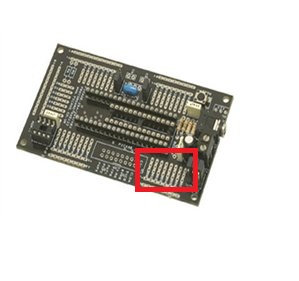
The red box is where I would think the servos would connect…
Any information would be great.
Thanks,
Joe
Outputs
I just read the manual and nothing weird jumps out at me. Your outputs (where your servo will be connected) are B0-B7. I think it is as simple as connecting to one of those outputs. The corner you indicate (with the red square) are indeed the outputs. Are you sure you are designating the correct pin in your code? Also, you may want to check to be sure you don’t need to move a jumper to energize the power rails at that location.
Thanks for the quick response.
Okay, I broke apart the 3 pin header and put ground to V0, volt to V+, and I know those are both working. And I also have the signal wire going to the correct pin. But its still not working all of the time. Occationnally, I think it will center but not always. I will upload a few pictures in a second.
I got it.
Thanks for the help. I was hooking up the signal pin, ground, and volt up to the same all to the pin. I thought the board was like the picaxe 28x project board were one was v+, one was ground, and one was signal. Here its all just one pin. Also I did not need the resistor. It is now working with out one. I think that was also messing things up. Thanks again.


