I need to know the smart servo motor (HT1) parameters ( the internal resistance and inductance and the inertia)
Hi,
Here is the information for the HT1 coreless DC Motor :
Terminal Resistance: 3.00 Ohm
Terminal Inductance: 0.65 mH
Rotor Inertia: 1.32 g.cm2
Hope this helps,
thank you @bdaouas
these values are what exactly i’m looking for but please can you also specify the torque constant, back EMF constant and motor viscous friction.
Based on the LSS HT1 performance graph that can be found in this Wiki page (which was obtained from our tests), these constants can be calculated. Here is the constants:
Torque constant (Kt): 0.6 N·m/A
Back EMF constant (Ke): 0.16 V/rpm or 1.5 V/(rad.s-1)
We certainly appreciate that you are asking these more in-depth questions regarding the servos. Although the primary market was intended to be beginners looking to easily experiment with smart servos, we are seeing many who wish to get a better understanding for more complex applications. Normally questions around back-EMF and constants is to model the servo - can you tell us a bit about your project or application?
First of all i want to thank you for specifying these information. And you are right about what you have just said, these information for modeling a 3 DOF manipulator system to be controlled using PID control. This is my graduation project and the main task is for trajectory planning for this manipulator.
Are you planning to physically create the robot or only a simulation of it ? Please feel free to post about it here if possible, would be interesting to know more about it.
Hi, i need to create a model for HT1 lynxmotion smart servo using simscape for pid control and i got the motor parameters from here :
High torque smart servo (HT1) parameters
motor model :
so i want to know is this model really represent the motor and what is the encoder gain (0.6667 is volt/rad if the encoder voltage is 4.096 volt). i implement this model to a revolute joint and take a feedback from the revolute joint block to the pid block and i hope by tuning i can specify the pid parameters.
@john97 Unfortunately beyond the specifications provided, RobotShop is not in a position to confirm or aid in the development of an external motion controller (or aid in the re-engineering of the internal motion controller). We do appreciate that you are looking to model the servo, and understand that ideally RobotShop would be as open as possible to aid with this, but for the moment we will need to leave it to the community to offer insights. This decision may change in the future, but for the moment, we greatly apologize for any inconvenience.
Hi, i’m working on a similar project and i also need to know these parameters. now i fortunately got these parameters but can anyone specify the viscous friction for the motor and the encoder gain ??
Hi,
Not sure what you mean by the “encoder gain”. The encoder IC inside the HT1 servo provides the information to MCU via I2C.
The minimum torque required to rotate the HT1 servo (unpowered) is 0.175 Kg.cm not sure if this value can help you calculate the viscous friction. Also, please note that this is an approximate value as it can vary slightly between HT1 servos and dependent on several factors (such as the quantity and type of grease put on the gears, the gears manufacturing tolerances, etc…)
Hi,
First of all i wanna thank you sir for your information…
In my mathematical model the input signal to my LSS motor , its type is volt or current ?
if it is voltage, and I want to rotate my motor i.e 30 degree, How can i control the value of this signal to get my acceptable output ?, and what is the type of the signal ( step, square …etc.)
also, if i want to use DAC waht its gain ???
Thanks 
Hi,
Smart servos are very different from regular RC servos (that takes PWM signal as input) or DC Motors (that takes analog voltage signal as input). Smart servos are controlled through serial commands and have their internal control. Therefore, a serial command of position (or relative position) is parsed with the servo’s MCU and converted into PWM signals sent to the servo’s DC motor driver which will rotate the DC motor accordingly.
You can only send serial commands to the LSS servo. These commands could be :
Absolute position commands (example: #0D900 to move the servo to an absolute position of 90 degrees)
Relative position commands (example: #0MD900 to move the servo BY 90 degrees)
Continuous rotation commands/wheel mode (example #0WR30 to rotate servo at 30 RPM or #0WD180 to rotate servo at 180 degrees/s)
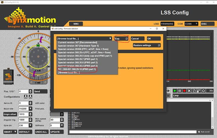
The servo doesn’t accept an analog voltage or current change as an input. However, we have recently implemented a new command called RDM.
This command can be used to send directly a duty-cycle value to the servo. For example, you can send a serial command of #0RDM512 to the servo, and the servo’s MCU will send a duty cycle value of 512 to the motor driver. This command has a range of values of [-1023, 1023], where negative values move the motor in the opposite direction.
This command is not available yet in the latest official firmware release v367 but can be found in the Experimental version 368.29.10. This firmware version can be found in the experimental firmware list of the LSSConfig software. However, please note that since this is still an experimental version, it is not thoroughly tested yet.


