Walter has (2) 7.2v packs, one for data and one for servos. Each has a switch and can be turned on idependantly (manually). During the "start-up" routine, I need the main picaxe to know if and when the servos have been turned on. It would be like this:
I turn on the main brain. The LCD turns on and displays a message to tell you to "turn the servos on, please" --I need the main brain to know when you have turned them on.
I need to send a simple data-level signal from a 5 volt source to a pic when that 5v source is running off one volt regulator and battery and the pic is running off of a different volt regulator and battery. Should I do this with a transistor? Diodes somewhere?
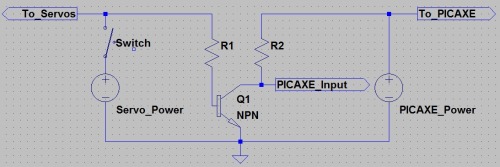
Hey CtC, here’s a little circuit that will do the trick. Note that the grounds, as usual, must be connected.
When the switch is open (no servo power), the PICAXE input is pulled high, thanks to R2. If the switch is then closed, Q1 turns on, pulling the input low. With sensible choice of NPN transistor and resistor values, this will work with just about any combination of voltages, and consumes almost no current. There is and even simpler option the uses just a diode and resistors, but it’s a little sketchy, and I figure you’d rather make something better for Walter =)
If you want to isolate the two circuits completely, even including the ground line, you can swap out Q1 for an optocoupler. It’ll be a little bigger than just a transistor, but should your servo power regulator blow up and blast your servo circuit with abnormally high voltages, the optocoupler will virtually completely protect the PICAXE side of the circuit. To be honest, the NPN transistor provides a fair amount of protection anyway, but since this is Walter we’re talking about I thought you might be interested in a more secure option as well.
Yeah an optocoupler would work great for this. We talked about their uses a long time ago, I don’t know if you recall that. Sparkfun has a couple different ones. Chrome isn’t liking links so I had to just paste it.
I use 10kΩ for all my I use 10kΩ for all my pull-up/pull-down resistors by default, and unless you use a really really crappy transistor 10kΩ will be fine for R1 as well.
Here is a proper thank you as your schematic worked perfectly. I was even able to solder the entire assembly in-line with a shrink-tube covering --no PCB’s.
Good solution, neat final product, the thing works… Badda Boom, Badda Bing.