Ok so followng the advice in this thread and from these forums I have now bought a 7.4v and an 11.1v Turnigy LiPo rechargeable batteries (different voltages to be used in different applications).

Ok so followng the advice in this thread and from these forums I have now bought a 7.4v and an 11.1v Turnigy LiPo rechargeable batteries (different voltages to be used in different applications).

Try L9110 driver module
The l9110 driver module can drive 2 motors within 2.5 - 9v, and drive 800mA, which are less than usual motor drivers, but can be improved with mini heatsinks.At least they don’t puff smoke when stalled.
Arduino Nano works fine even when provided 4.8v at Vin, but you can’t use the 5v regulator, you must connect battery+ to AREF to get good analog values, and it goes slower, but i couldn’t test it. The HC-SR04 works enough at 4.8v (avoid crashing on walls).
In the breadboard above just wire everything can take 7.2v to the battery, everything else to the 5v regulator of the L298.
Sorry for not replying
Sorry for not replying sooner as I didn’t get any notifications saying that there had been any replies??
Anyway, today I made up a connector for my 7.4v LiPo and connected the V+ to the Vin of the L298N via an SPST switch.
Everything was powered from the L298N 5v Output and after checking and making a few amendments to the code it actually worked. The servo sweep is way too fast and the motors also need slowing down (although I did amend the speed in the code), but it moves forward stops when it detects something, the servo scans left and right and it then finds a clear route and moves forward again.
Its a little clunky but as this is my first ever autonomous obstacle avoidance robot its a milestone that can only be improved upon.
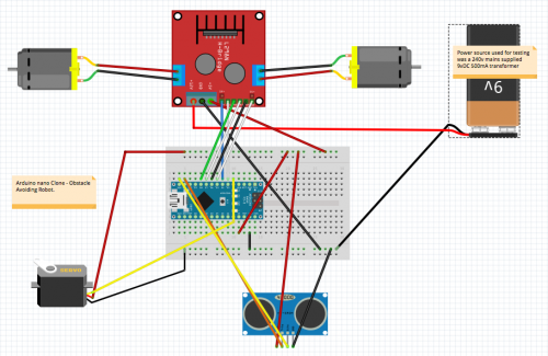
I’ll make some tweaks to the circuitry and power supplies as recommended by you fellas and sorry about the bad schematic using Fritzing but we aren’t all born experts and learn something new every day. (I had never seen Fritzing before using this Forum and I think as a freebie its damm good).
Here’s a slightly amended diagram:

I'll start up a Blog and post up some pics and a video.
Just a comment about the way you show power rails on the
breadboard.
Typically, I see Power and Ground on both sides of the breadboard. The small, cheap boards I bought on eBay actually have Red and Blue lines to suggest Power and Ground on each side rather than Power on one side and Ground on the other. Maybe you just drew it that way because it was easier. If you check eBay, you will see a number of breadboard voltage regulator boards that span the two rails to allow you to have either 5v on each side or maybe 5 on one side and 3.3 on the other, or, some variation of the previous, maybe even 1.8v.
Long drawn out conclusion is, you may want to actually have Power and Ground on each side of your breadboard for convenience. You can even tie both sides together with a pair of looped wires from one side to the other.