Hello all.
I'm completely new to your world and am building a kind of robot that's a bit out of your usual line - this robot makes vodka!
Seriously, I'm an experienced amateur distiller in New Zealand - where home distilling is perfectly legal. I build my own stills as well as use them.
My latest project is to build a completely electronically controlled vodka still of the kind available to major distilleries ( at huge cost ) on a hobbyist budget.
I can handle the electronics on an arduino, the welding in my shed and have worked out how to sidestep the expense of multiple accurate temperature & pressure sensors.
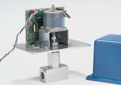
But I just can't find a simple coupling to join a stepper motor to a needle valve and I'm hoping that someone here is clever enough to work out a practical, durable, sensibly sized & inexpensive solution. Some custom machining is almost certain to needed at the valve end of the coupling and that's fine.
The problem is that the gap between the end of the stepper motor drive shaft & the top end of the valve stem is not constant:
as the stepper motor turns the valve stem to open the valve, the top of the valve stem rises towards the stepper motor and visa versa. So the gap is constantly changing as the motor adjusts the valve.
The axial travel that I need to accomodate is at least 2mm and perhaps as much as 5mm. I will not know until we start determining the valve travel needed by experimentation.
I know it can be done because there's a commercially available unit - at insane cost and using inappropriate valves for my application. But the picture shows exactly what I want to do.
Any brilliant ideas to help me would be hugely appreciated.


