Auto-Dock Robot Board Buildup
This week was a board buildup and install of the remaining circuitry for the Robot. The charger requires some pretty heavy mods and I’ll be working that next week.
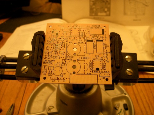
Bare board. Both the Robot and the Charger are the same PCB, but there are small changes of parts lists and configuration that make the boards react differently. Kind of smart of Heathkit. ( and I forgot the flash again )
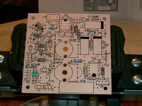
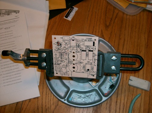
Soldering on a couple resistors and Caps.
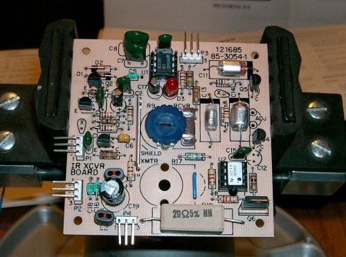
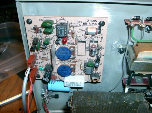
Completed board for the Robot. R-17, C-12, and ADJ are not used on this board.
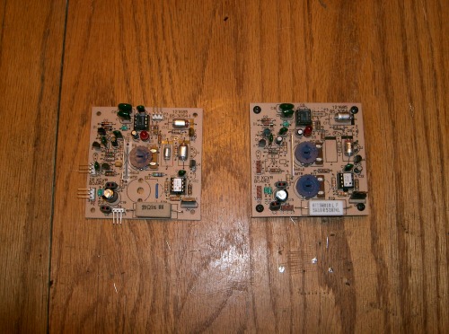
Here are both boards assembled the one on the left is the Robot board, the one on the right is the charger.
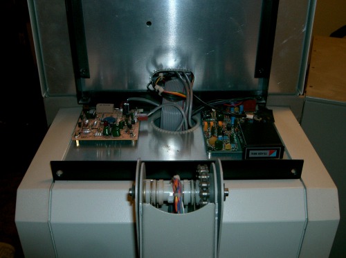
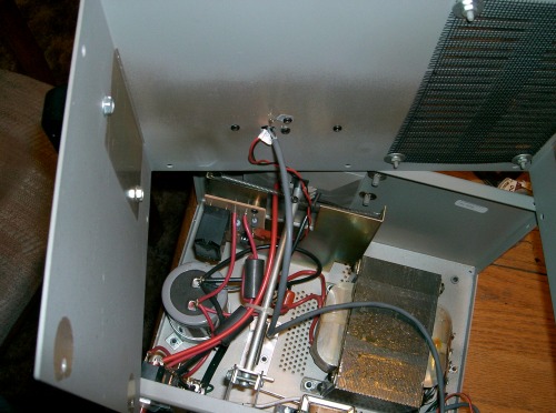
Installed in robot, There is one more thing I have to build before the hardware is completed. the harness that goes from the I/O board to the dock board.
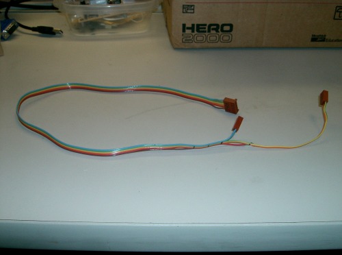
The Harness, you notice the there is a stray that goes in to connector S-1 when installed.
Well that's it for this week (Feb 24,2012) From the ManCave of North Edwards. Next week will be Final install and checkout of system in the robot. Then I'll tackel the charger.
Kevin
The next board build-up is one for the charger. Blank board. I'll spare the rest. show the completed board and show the charger breakdown.
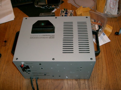
Back of charger.
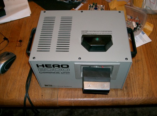
Front of charger.
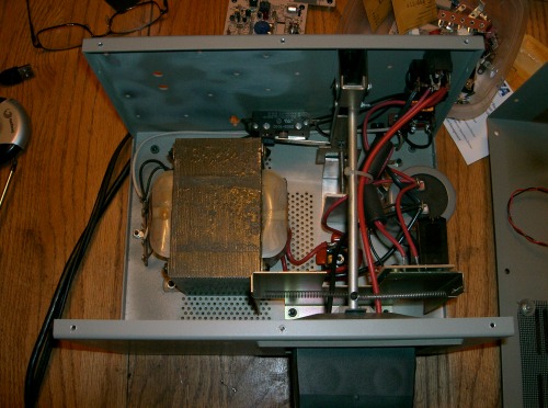
Cover off to start mods. First thing is to remove the paint form the ground mounting points.
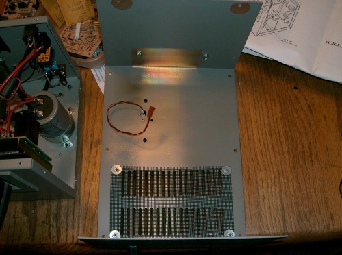
Cover to be set aside and worked on ( next week)
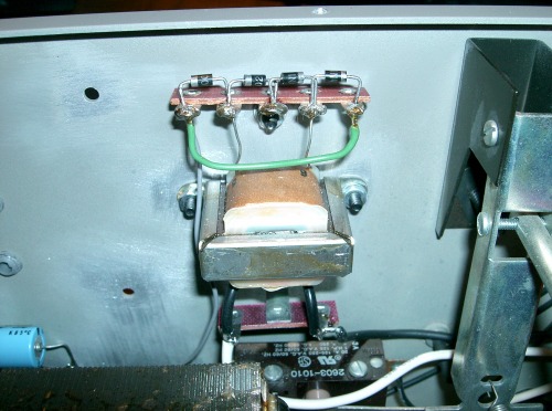
Insert terminal tab for the 115VAC protion of the transformer (power supply build up for the circuit board.
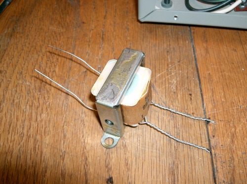
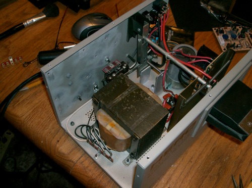
Confirgured the transformer for 115Vac. Produces 17Vac on the backside after recification.
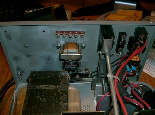
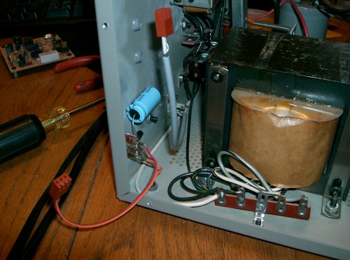
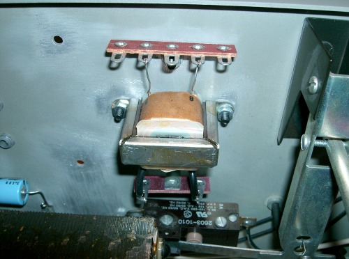
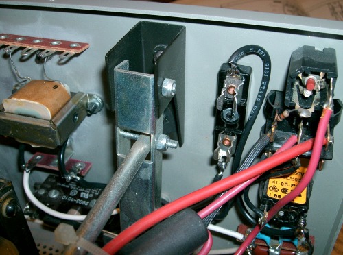
Transformer installed in the charger.the Tab terminal above the transformer. The rectifier (diodes )will be soldered to the tabs
Installation of Voltage regulator for the charger board.
Next series of pictures shoes the wiring of the power supply for the board and the RCA jace for the mirror detector.
Addition of fuse block.
Diodes full bridge rectifier.
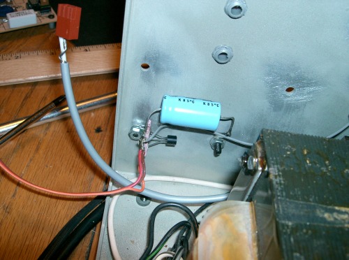
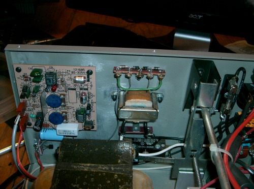
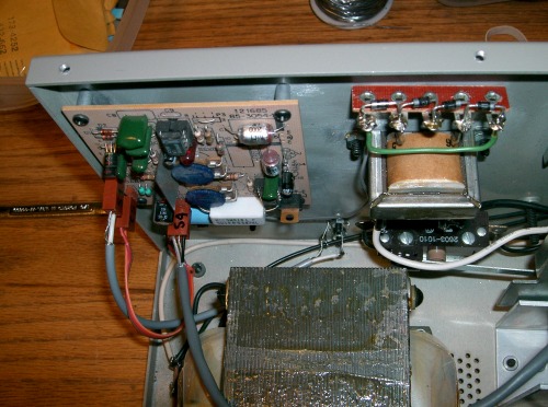
Wiring Completed in the charger.
Closer look at the board installation.
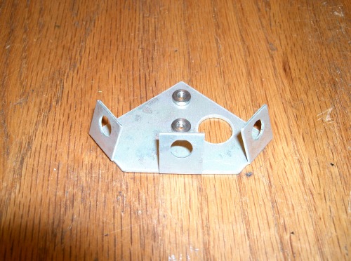
IR LED mounting plate for the charger top.

With LED holders. Well that's it for this week at the ManCave of North Edwards. (3/3/2012)
Next week I should be finishing up with portion of the project. Video will follow.
Kevin
The Next set of pictures is for the Charger Beacon and Detector builds. This is the last of the assembly before testing the system in the robot
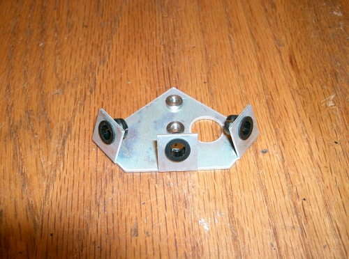
Photo show the build-up of the Charger beacon plate and IR LED holders.
IR leds installed. and the beacon is mounted on the top cover of the Charger.
. IR LEDs are all wired up. Beacon cover un-installed
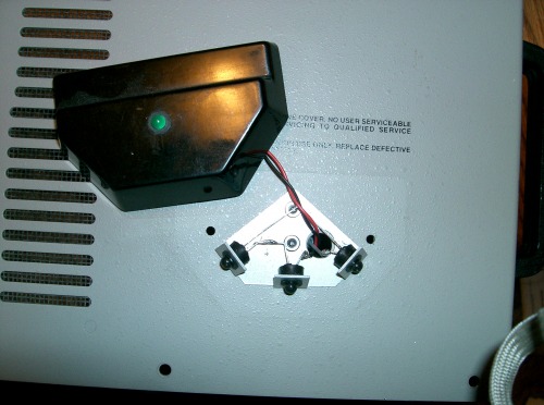
Top view.
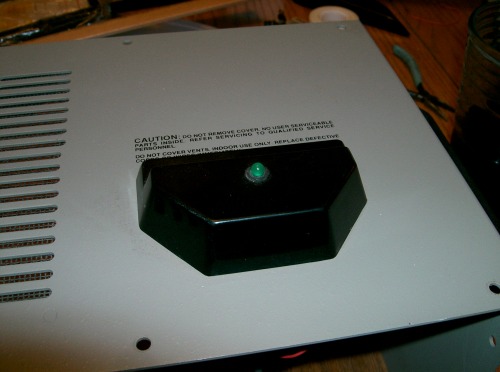
Beacon Cover installed
Beacon Plug S-4 installed on board.
View of lid about to go back on. Note the grounding tab for the shield of the wire on the back side of the lid. Charger Completed on the the Charger detector.
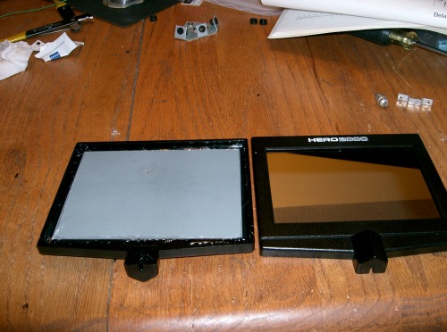
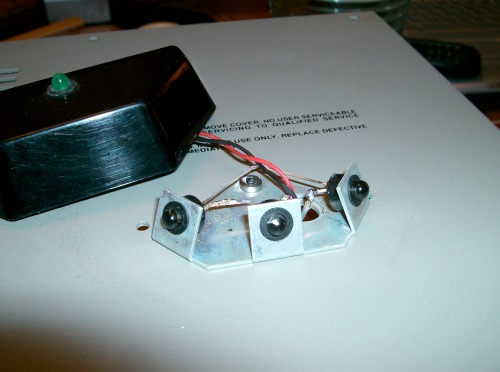
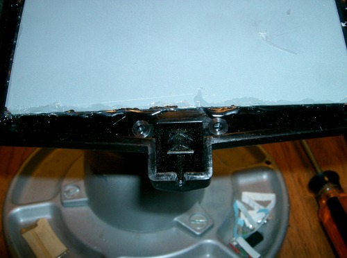
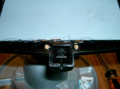
I found a Second Mirror that wasn't built ( so I'm building two. ) showing the front and back. I used Hot glue to attach the mirrors to the frames rather than the Epoxy in the kit (20 plus years old), To me it's less messy, and easy to apply. Epoxy belongs in the Wingboxes of model airplanes.
THis picture shows the empty detector cavity where I'll be placing all the bits and peices into.
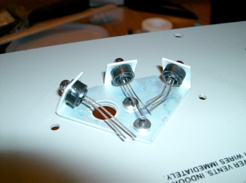
Insertion of brass fittings for the Photo doides.
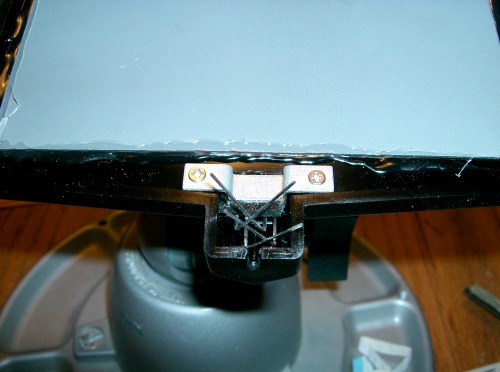
Diodes and bracket installed.Both anodes and cathodes are crossed together for wiring installation.
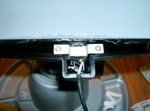
Coax soldered to the Photo diodes.
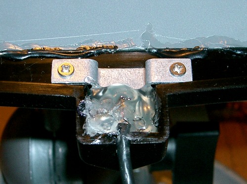
One can never use enough hot glue...
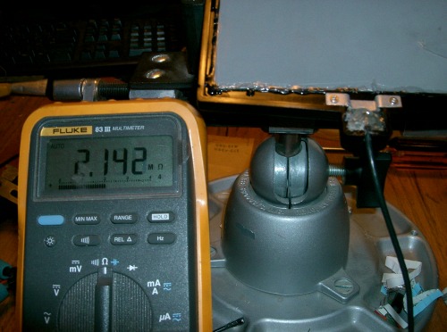
Function check of the Photo diodes. Exposed light.
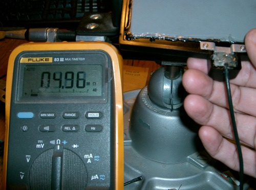
And in the dark. I do these little checks along the way to help with any trouble shooting efforts that may happen later.
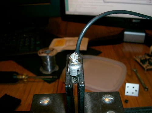
Finished up by soldering and Hot gluing the Coax to the RCA jack.
That’s it this week from the ManCave (9/March/2012) Next week, Systems Checkout.


