

This baby takes input from a home made scripting language and turns it into drawings on the floor.
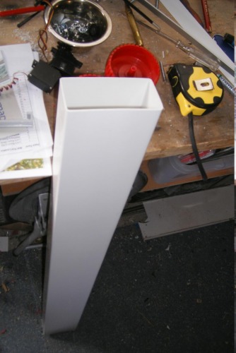
When I rule the world, PVC conduit is going to be what all robots are made from. You have an easily workable, light, smart material ready for making L-sections, U-sections, boxes... You name it. Here's a piece which is just busting to get turned into a robot.
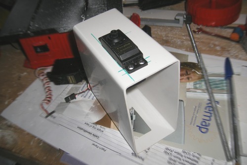
Mounting the servos is a piece of cake. Cut a pair of parallel lines with your mini circular saw, drill half a dozen 2mm holes across each end, cut the rough off with a sharp knife and there you have two servo mounts. You could mess around drilling holes for bolts or plastic rivets, or you could just drill 2mm holes close to the centres of the servo mounting holes and attach it with self-tapping screws.
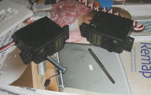
There is quite a distance from the outside wall of the wheel and the servo head. Fortunately, there is an equally long axle inthe middle of my chosen wheels. This means an extra long screw is needed to hold the wheels onto the servos. I don't think you get 30mm long self tappers, so I tapped the holes in my servo heads out to 3mm so I can just stick any old M3 bolt in 'em. The motor on the left has such a bolt inserted. In the foreground, you can see my tapping tool.
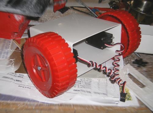
This is the chassis with the wheels mounted. I bored the axles out to 5.5mm. This is a reasonaly malleable material, so I warmed them a little and forced interference fitted them onto the servo heads. It appears that the head has cut (or pressed) perfect grooves into the plastic, so now the wheels can be attached and detached just like any servo horn.
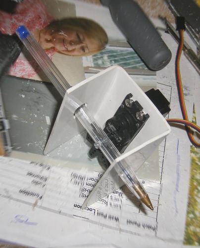
The pen mount is a U-section of the PVC. There's a hole top and bottom through which the pen passes. The hole on top is elongated as the pen top moves side-to side as the servo horn turns. There's a 2mm hole drilled through the pen and an M2 bolt through it into a tapped hole in the servo horn.
This is a close up of the bot mechanically complete. At this point, I decided that although the bot moves forward and back with the same economy, it needed to have a "back" and a "front" to facilitate the programming of directional components. Later, I was reminded that if we accelerate a lightweight co-axially driven robot, the "front" end rises (it does a "wheelie"). This would cause the pen to rise off the paper - no good if you want to draw stuff. So, the pen end was nominated as the "back" and a mental note made that I should only draw while moving "forward."
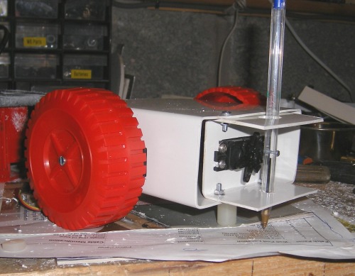
At the back you can see a peg at the bottom. This is the third balance point when the pen is up. This peg lifts off the page when the pen is down and the pen becomes the third part of the tripod.
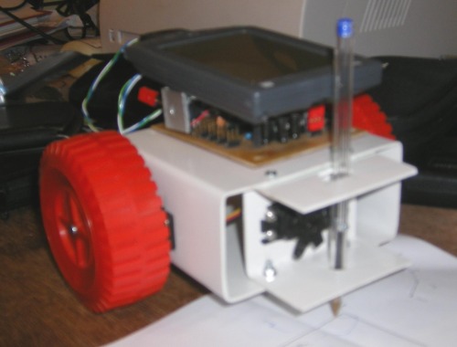
Currently the robot is controlled by an RS-232 link to a desktop PC. This is a rubbish photo of how it might look once I mount a Palm Pilot as a controller on the robot in order to remove the umbilical.
I modified the main drive servos for continuous rotation (documented in loads of places on the web). After the first few experiments I realised the speed control with continuous rotation servos is actually remarkably difficult. My servo controller allows me to send out a servo pulse between 1ms and 2ms in length. Logically, a pulse of 1.5ms would cause the motor to stop. Two points:
1) Unfortunately, I found that unless you use extremely high tolerance (read "expensive") resistors to build your potential divider, the midpoint (at which the motors will stop) wil be different for each motor modified.
2) The resolution of my speed pulse is 8-bits. It's a 2's compliment value between -128 and 127 where negative numbers are "backwards" and positive "forwards." I found that anything outside the range -5..+5 full speed.
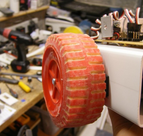
The result of the rambling story is that I decided that the best thing to do was always operate at "full on" speed and first tests showed that this caused the wheels to spin on the paper! So, I gave the wheels a couple of coats of liquid latex. Now they stick like slicks on a hot F1 racetrack.
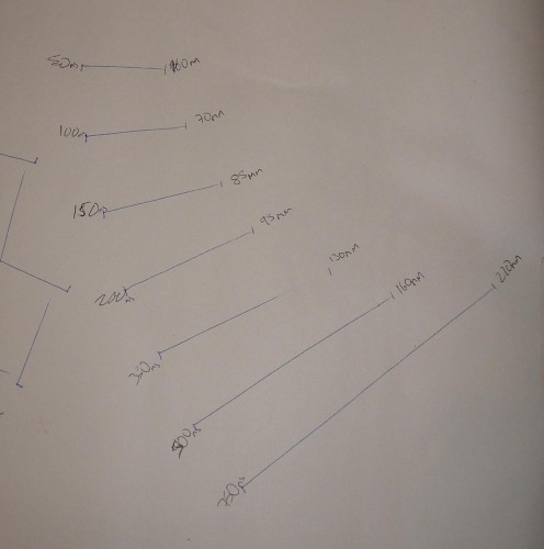
There is no positional feeback from the servos, so some calibration was necessary. "How far do I get in 100ms?" was the key question. I had the bot draw straight lines for a selection of known times as shown in the photo and made a note of how long the resultant line was. I bashed this data into MS Excel and it squirted out the formula: d = 0.227 * t + 49.051 where d is the distance in mm and t is the time in ms. The spreadsheet is included here. This is the calibration lines. They were expected to be parallel, having been drawn by a repetition of "pendown, forward, penup, backward, right 90, forward, left 90." You can see they're not parallel, but convergent (having been drawn left to right). So at this point, there is evidence that the rightmost motor is more efficient than the left.
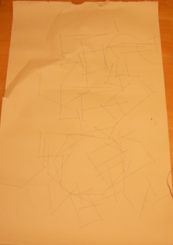
Here are some scribbles the machine made when I was trying to figure out how long to keep the motors on in order to make certain angles.
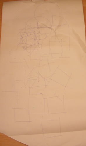
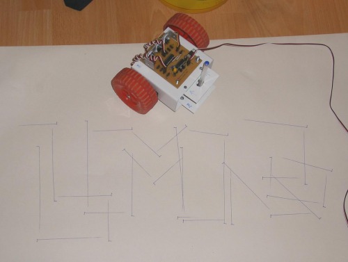
This is the result of the first attempt to write LMR in block outline font with straight lines only (no curves). As you can see, I'm falling down on my R's. (Ha ha ha.)
Electronics
The control board is the one I made for the walking biped. It works for continuous rotation servos without any software changes. The scriping language I wrote for that project has been extended to support the floor turtle. For all the geeks amoung us (oh, wait - that's everyone), I've also attached a copy of the script used to draw LMR in block text.
History
I've been wanting to do this for ages. I just thought "Nah - it was done 40 years ago. Nobody would be interested." (Speaking of 40 years ago, check ou the upside-down trash can halfway down this page.) Then Frits posted it as a competition. Now I've done it.
Curves
A brief note on curves: They aren't going to happen. Drawing an "R" with straight lines is a nightmare. Curves are a double nghtmare. I actually looked at the format for TrueType fonts. It's not that difficult to read and I could probably interpret them with a few days work, but can I approximate curves with this bot? Nope. Unless it's the curve you get naturally just by spinning the bot.
Writes and draws on the floor.
- Actuators / output devices: Two drive servos modified for continuous rotation and one stock servo for pen up/down.
- Control method: Under scripted control from a desktop PC by serial cable.
- CPU: PIC 16F628
- Power source: 6xAA NiMH
- Programming language: Turtle is in PIC RISC assembler. ServoScript translator is in LabVIEW. ServoScript is a homemade language.
- Sensors / input devices: None.
- Target environment: indoor, flat floor, on paper
This is a companion discussion topic for the original entry at https://community.robotshop.com/robots/show/harmenszoon

 Watch this space.