UPDATE
Oct 8, 2012: I have made a small PCB adapter to complement the GOduino III to enable 90 degree positioning of directional sensors such as ultrasonic and IR proximity sensors. I have posted the details here: http://www.instructables.com/id/Plug-your-sensors-on-the-breadboard-at-90-degrees-/
INTRODUCTION
This is my first PCB project so I would appreciate the feedback.
The GOduino III is an Arduino compatible Open Source Hardware robot controller. It's a simple and inexpensive robot controller (appx. $25). I built this controller for my robotics workshops as well as for my personal projects. The GOduino III can be inserted into a breadboard for easy prototyping. The GOduino III comes with a software library to support motor functions.
The GOduino III is based on the ATmega328p microcontroller and the L293D dual h-bridge. It's built with DIP ICs and through-hole components for ease of assembly and repair. This robot controller can handle 2 small servos and 2 DC brushed motors (max 1.2A for each motor with 2 X L293D).
The GOduino III can be programmed with a standard Arduino IDE via an FTDI USB/UART programmer or via the ICSP header using programmers such as AVR-ISP, STK500, or parallel programmers.
This is a 3rd generation GOduino. The one before was the prefboard GOduino II.
SPECIFICATIONS
- Based on the ATmega328p microcontroller @ 16 MHz (the heart of the Arduino Uno DIP model)
- Size: 5cm X 2.5cm.
- Plugs into a breadboard with the help of 0.1" (2.54mm) male headers or you can solder female headers.
- Arduino standard digital, analog, and special purpose pins exposed.
- Digital I/O Pins: 14 (of which 6 provide PWM output) - Analog Input Pins: 6
- 2 X LED: one for power and another for pin 13.
- Reset button.
- 2 X 3-pin 0.1" (2.54mm) headers (5V) for small servos.
- 2 X 2-pin 0.1" (2.54mm) header for brushed DC motors.
- 6-pin 0.1" (2.54mm) ICSP male header.
- 6-pin 0.1" (2.54mm) male header to accommodate FTDI USB programmer.
- Flash Memory: 32 KB of which 0.5 KB used by bootloader
- SRAM: 2 KB
- EEPROM: 1 KB
PROGRAMMING
- The GOduino III can be programmed with the Arduino IDE via an FTDI USB programmer
- It can also be programmed via the ICSP header using programmers such as AVR-ISP, STK500, or parallel programmers.
- The FTDI "FT232RL USB to Serial adapter" can be purchased for less than $10 from Ebay.
- Also, you can use an Arduino Uno DIP to program the GOduino III ATmega328 microcontroller then insert it back into the GOduino III.
- Auto-reset capability for FTDI programmers via the DTR pin.
POWER
- Logic Voltage: 5V supplied by the T7805CV regulator.
- Input Voltage (recommended): 7-12V. (limits): 6-20V
- Motor Voltage: While the L293D motor driver IC is rated for 4.5V to 36V, we are bound by the recommended/limit voltage ratings of the power regulator.
- 1N7001 diode protects against reverse voltage from the external power source.
- The L7805CV regulator provides 1.5 A which is enough to power the GOduino III and 2 small servos.
- You can swap the 7805 with pin-compatible low-drop out voltage regulators with higher current such as the LM1084-5V which can source 5A with a maximum dropout voltage of 1.5V.
- The 5V regulator also powers the servos but not the motors.
- For the motors, the L293D h-bridge gets its power from the DC jack or from the VIN pin directly.
- You can select to power the GOduino III from USB or External power with a pin jumper. Please note that USB power may not be enough to operate servos and motors.
- The L293D h-bridge can supports 2 DC motors @ 600mA continuous current each. You can piggyback two L293D to double the current to 1.2A per DC motor.
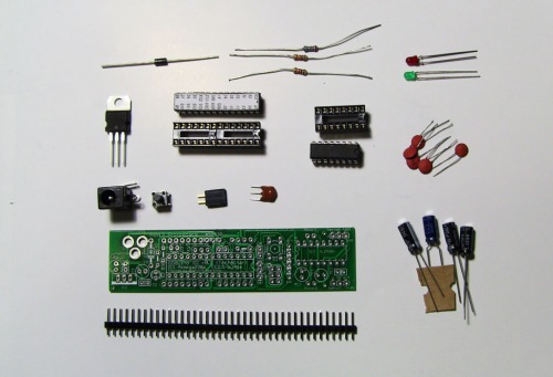
PARTS
| Part | Qty |
| Capacitor ceramic 0.1uF | 5 |
| 10uF/25V | 1 |
| 100uF/16V | 1 |
| 100uF/6V | 2 |
| Diode 1N4007 | 1 |
| LED Red 3MM | 1 |
| LED Green 3MM | 1 |
| ATMEGA168P Microcontroller | 1 |
| 7805 5V regulator | 1 |
| L293D dual h-bridge | 1 |
| DC Jack female 1X2-3.5MM | 1 |
| 40-pin male header (0.1" 2.54mm) | 1 |
| Resistor 10K | 1 |
| Resistor 1.0 K | 2 |
| Reset button | 1 |
| 16.00MHz Ceramic resonator 3-pin | 1 |
I am considering replacing the 3.5mm DC power jack with a terminal block for the next patch of GOduino PCBs.
You can get the EAGLE schematics for the PCB from Github along with the library. The board layout is being modified but I will post it to Github soon as I am done.
BACKGROUND
This is a 3rd generation of GOduino robot controllers which I began in March 2012 with the breadboard version, then the pref board version, and now this PCB version.
SOFTWARE LIBRARY
There are 4 functions in the Goduino library:
- motorSpeed(mot1speed, mot2speed) Sets speed for both motors
- motorStop(motorNum) Stops a motor
- motorForward(motorNum) Spins a motor in one direction
- motorBack(motorNum) Spins a motor in the reverse direction.
The 2 servos are controlled by the standard Arduino servo library.
The pins between the ATmega328p and the L293D are mapped in this manner:
Motor 1 Pole 1 ---> Arduino Pin 4
Motor 1 Pole 2 ---> Arduino Pin 2
Motor 2 Pole 1 ---> Arduino Pin 7
Motor 2 Pole 2 ---> Arduino Pin 8
Motor 1 Enable ---> Arduino Pin 5
Motor 2 Enable ---> Arduino Pin 6
NOTE: I have avoided using Arduino Uno pins 3 and 11 because they are used by the Arduino tone() function. So now I can build a robot that makes noise. (applause).
https://github.com/techbitar/goduino
VIDEO
CREDITS
Special thanks to my good friend Jafar Quttaineh for his invaluable suggestions. The GOduino III form factor was inspired by Adafruit's Boarduino which is an Arduino clone that can be plugged into a breadboard. Using this form-factor for the GOduino III makes prototyping robots for newbies much simpler. (adafruit.com)