

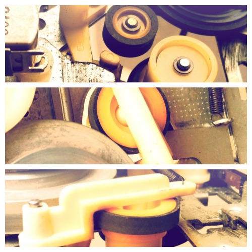
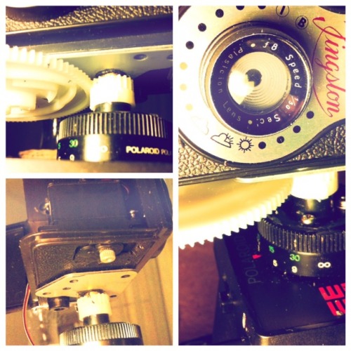
Head can rotate now using a gear from an old vynil record player.
Chapters
1. Meaning of Life
2. Let's start making
3. Let's continue making
4. Let's learn some microphone theory
5. Prepare the head
6. First throwback: Head rotation
7. Turn the robot on and off
8. The Software: State Machine
9. Driver and Track Drive Software Made
10. Track Drive Software Integrationtest
11. Hierarchical Control System
12. Remote Control to simulate the direction
13. Mash up Behavior
14. Find out where to go with closed eyes
15. Electronics for the Head. Use closed eyes and ears
16. Head's up
17. Head rotates (new)
Introduction
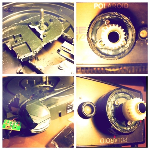
Looking around for a base for my next robot diy project I found an old Polaroid from the eighties. It was waiting for me hidden underneath a thick layer of cables in a box in a local thrift store.
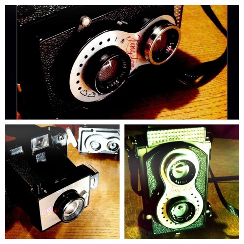
I know that there is plenty of those Polaroids out there but no one has filmmaterial for them anymore. They got quite useless. So having this in mind there is nothing in the way to hack this device an make a robot out of it. The next day I found a Kingston twin lens reflex camera in another thrift store. Very light plastic. Good for a moving robot head. So the idea of a photo robot got momentum and some engineering time.
1. Meaning of Life
Fhotibot's meaning of life shall be, that he wanders around and takes pictures. To make shure the pictures have a slight chance of showing something interesting the Fhotibot shall have some strategy. The first strategy to find something interesting is to follow noise and get there. Find where it is loud. Then take pictures.
Fhotibot will live and work in our apartment. He has to deal with wooden floors, doorsteps between the rooms and children playing with it. Children means it has to be robust. Doorsteps for the Fhotibot means tracks.
To tackle the given strategy Fhotibot shall have some tactics:
- It can move autonomously and avoid obstacles.
- It can determine where the noise is and go there.
- It can take pictures from where it thinks is important.
Fhotibot shall have some tools.
- First it shall be able to measure distance close (1-3cm), mean (4 - 80cm) and long (80 - 500cm).
- Second shall be able detect and measure noise/sound.
- Then it must be able to command motors and servos.
- Further it must have a camera to take pictures.
2. Let's start making!
Here the two cameras for the motor body and head.
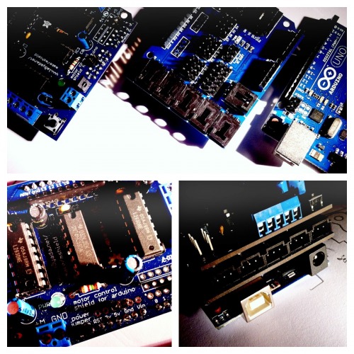
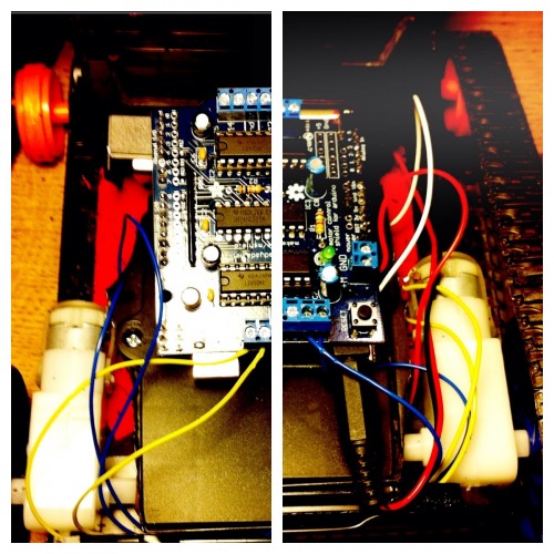
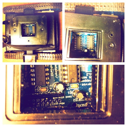
Arduino Uno, Arduino Sensor Shield V4.0 and Adafruit Motor/Stepper/Servo Shield. All three stacked fit into the shaft of the Polariod.
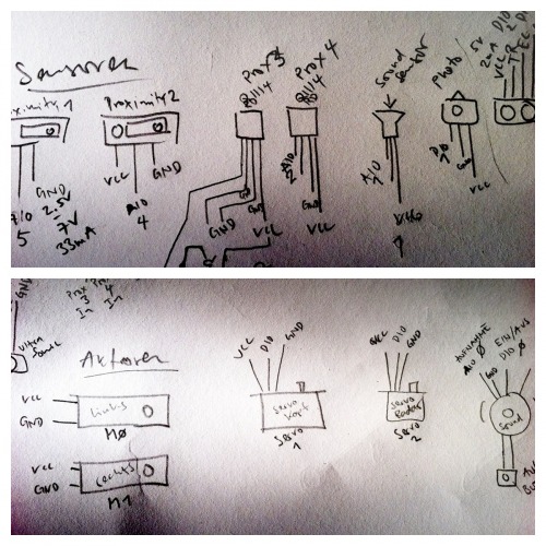
Sketch of the actors and (planned) sensors.
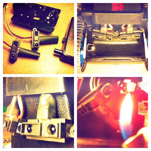
Each part gets breadboarded, tested and integrated into the controlling.
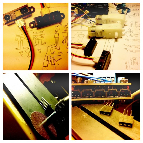
Unfortunately the proximity sensor has a different plug standard so I cut an adapter. Now I have nice little adapters to connect the sensor to the sensor shield.
All actors are ready now and smoke tested.
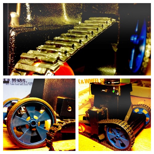
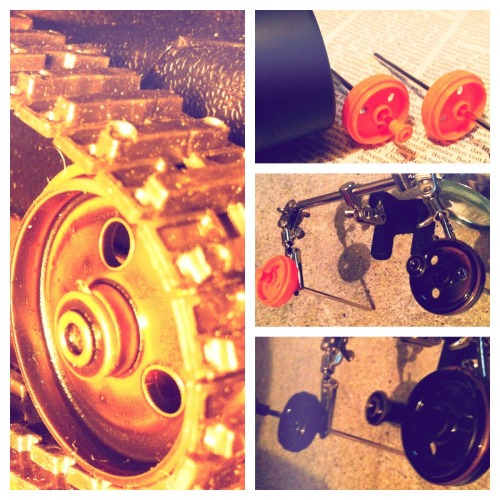
It turned out that the Solarbotics G3 224:1 ( http://www.solarbotics.com/products/gm3/ ) fit (almost) nicely into the Polaroid. They get embedded into the Polaroid. So I cut out as much as needed that the wheel can be positionized as nessesary.
Gearmotors embedded. Now the freerunning wheels must be added and the whole system calibrated.
Now the camera enters slowly into it's second life. Since I want to keep the cameras as original as possible only a few things get cut away like this little channel through the viewfinder.
Now it is time for the first system tests...
Tracks on - first challange solved
But there is still a lot todo. The head, sensors, software and the camera. Maybe I can use an old mobilephone as Fotibot's cam. We'll see.
3. Let's continue making
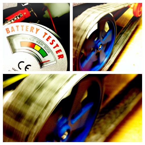
Since Fotibot is energized by battery I integrated two battery packs in the base of the robot.
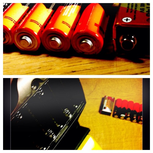
As battery pack I use a part from an old remote control. It is flat and takes six AA batteries. That is what is enough for the gearmotors. The battery pack is extended with a hinge-joint. The hinge helps me to extend the robot with more frontsensors if nessesary. Just lift it up and insert. Some +/- cables wired.
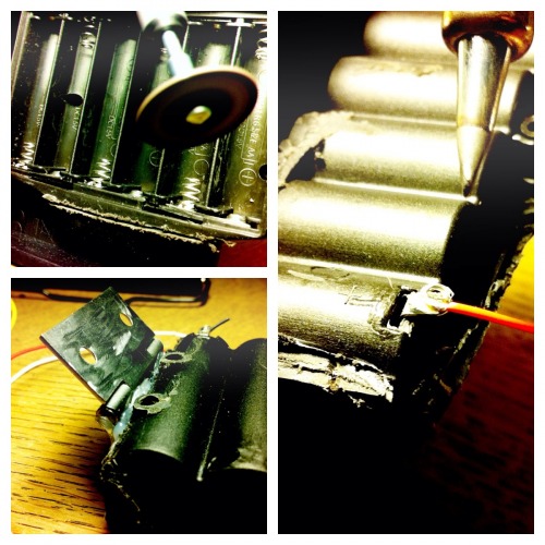
Now the battery packs and motors get final integration. By the way: The Polaroid is Made in the UK. Have not seen this for a while.
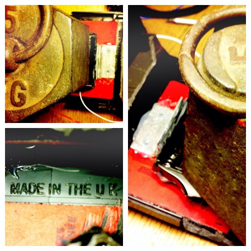
Here the battery pack is lifted upwards. I think I have to insert some more axis at the bottom.
It is time for an integration test of the hacked battery pack and motors again.
All good. Nice.
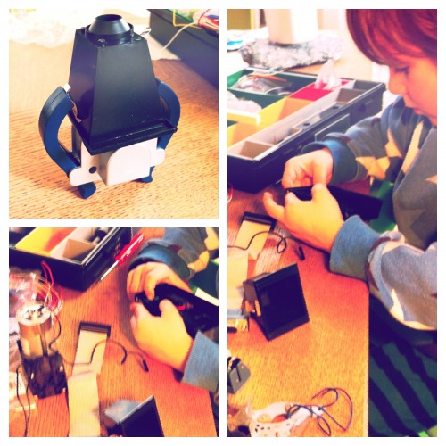
The Arduino and the two shields match perfectly into the shaft of the camera. Battery packs closed. One 9v battery directly behind it for the Arduino.
Energy in - second challenge solved
Using old parts to make something new is fun.
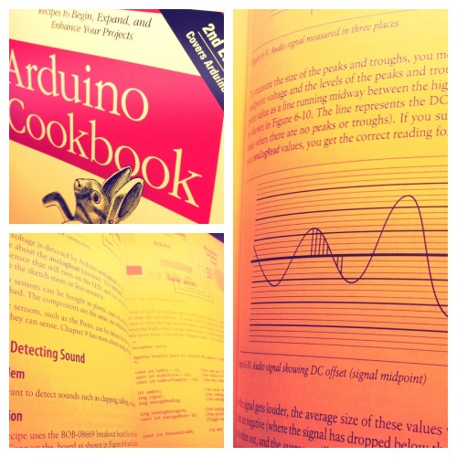
4. Let's learn some microphone theory
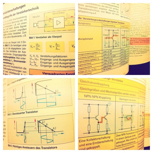
Since Fotibot shall find where it is loud it needs some sound detection and ability to spacial locate the source. The shown book contains knowledge about that and some code that samples the analog input and calculates an average so that the input signals are useful.
After a while I had calibrated the sound sensor and could detect very little to loud noise. Green lamp off - no signal. Green lamp on - sound detected.
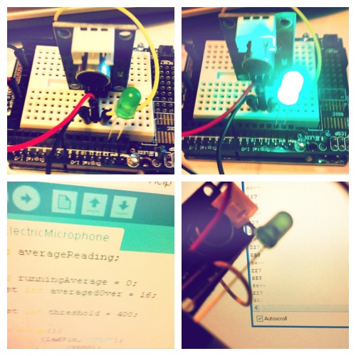
So I tried to connect a regular microphone... but since the signal was so low the Arduino detected nothing. So I continued studying theory about amplification...
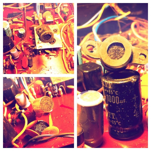
Instead of soldering my own multi-stage amplifyer I thought maybe take it with a mic from an old tape recorder.
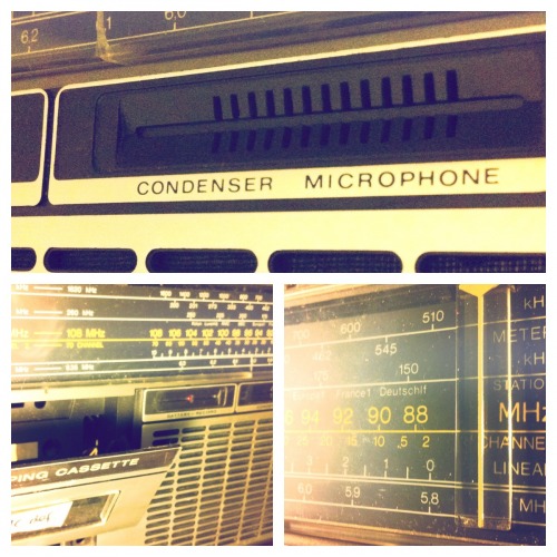
Well should I take this one? Maybe not. Fotibot needs minimum two microphones, maybe even three.
I think I have a look at eBay.. maybe there is some matching mic and amplifyer for a good price for the Fotibot.
Sound detected - third challenge solved
Next challenge is the head assembly. A robust rotateable assembly.
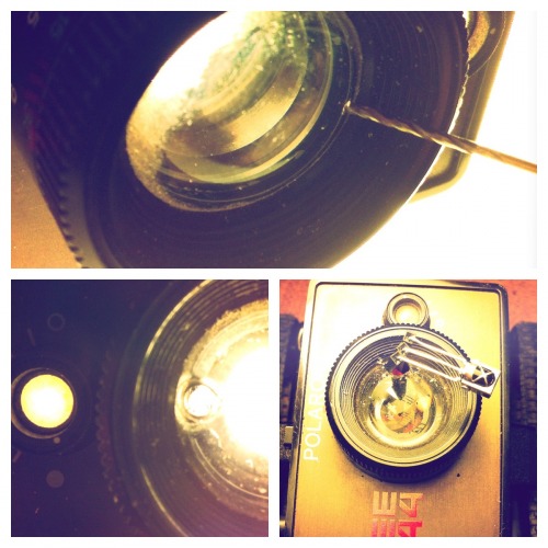
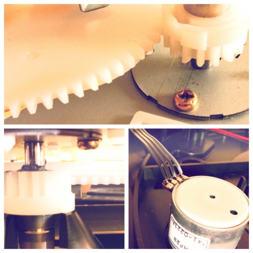
5. Time to prepare the head
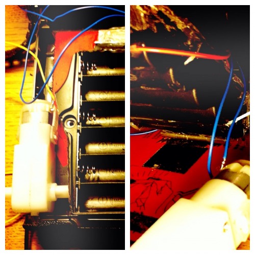
The head must be rotateable and hold tight to the body. I thought best to use the existing lens shaft as a mount for the head and the former exposure adjust knob (small black) as the rotateable unit.
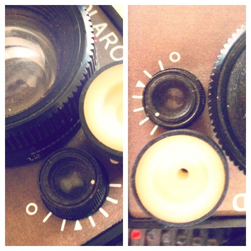
As an option there is a wheel from the old tape recorder.
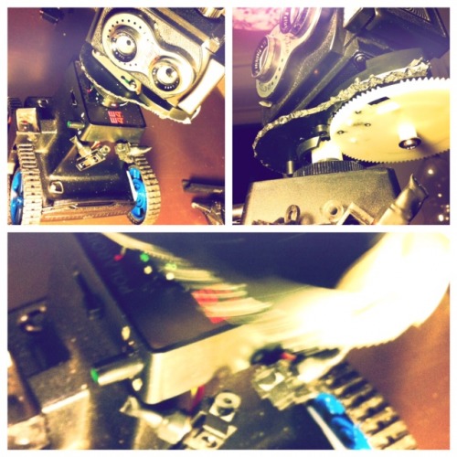
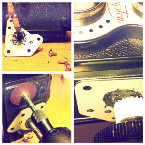
To use the exposure knob with a servo or stepper motor I had to clear the area, grind a space for the servo connection into a wheel from the tape recorder, reduce friction with oil in the knob and prepare the servo.
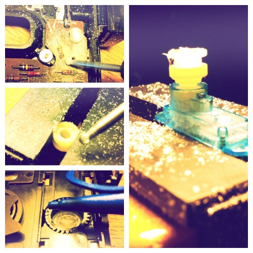
Removing the head parts gave me that insight from above. The motor driver with the Arduino in the shaft of the Polaroid.
The orange track wheels got painted rough black... the orange did not fit into the mood board of Fotibot..
After a while I got some help from a young maker.
6. First throwback: Head rotation
The initial idea was to use the exposure knob as the rotation driver. I tried a micro servo but the rotation of 180 degrees is not enough to rotate the big lens wheel. Then I tried the continuous servo... but this beast is not precise enough. Precision is needed since the angle of the head is used for path calculation. Last I tried the little stepper motor. Good results. But the motor is not strong enough to move this small-knob-to-big-knob pre existing gear on top of the Polaroid. So I need to elaborate on this topic more and maybe say good-bye to the small-knob-to-big-knob gear and to mount the big knob (the camera lense) direct to a servo.
7. Turn the robot on and off
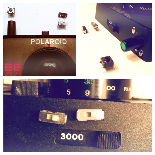
To turn the Fhotibot on and off I now know how to embed this into the camera. I hack the top two knobs using small knobs from the Arduino starter kit. Two slide knobs: one for the microcontroller (9V), one for the motors (12V). Both have to be on or off at the same time.
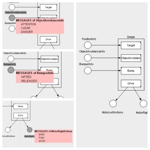
8. The Software: State Machine
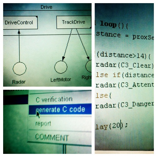
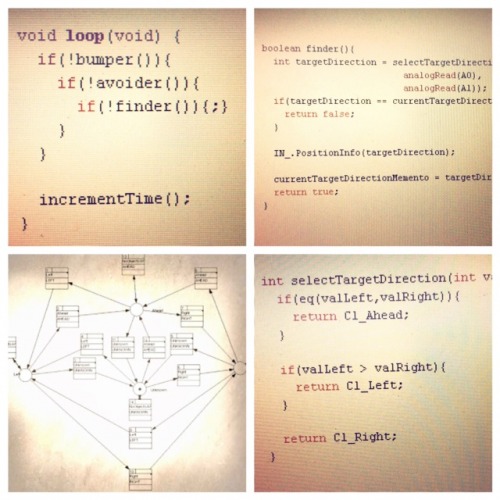
After all this cutting, grinding and exploring the robot's body it is time to start with the software. Tired of all these if(..){..}else{..} and switch(..){case:...} code it was time to leave procedural programming and move on to state machine programming. This computation model fits perfect to what the Fhotibot is intended to do.
The CIP Tool is my prefered choice here since it is very lightweight tool based on a well engineered theory and: it generates C and C++ code. The C code (have not tried the C++ code yet) can be run on the Arduino. Straight forward. The sensor values are streamed into the state machine where the motor behavior changes to the defined state.
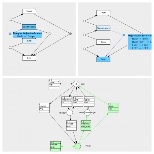
Here two images from the current simple motor behavior.
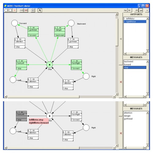
9. Driver and Track Drive Software Made
Supported by team fellows during coffee breaks I continued to develop the automation software. Straight forward design I'd say. Using CIP the control- and drive software-components are modeled as a reactive system with state machines. The system is then exported to plain old C and imported into the Arduino IDE. The connector code from the system to the arduino-loop and the sensors is handcrafted.
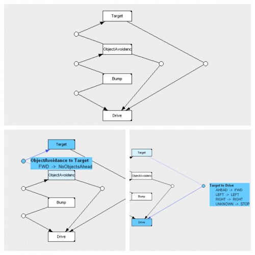
This control makes the Fhotibot go forward as long the path is clear. When attention needed the Fhotibot (for now) turns to the leftside. It does that until the path is clear and it goes forward again. In danger the robot goes backward and tries a three point turn to the right.
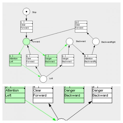
The drive coorinates the two motors and knows when the two motors must be stopped, back- and forwarded to make the robot move in the desired direction. Their knowledge is very track specific.
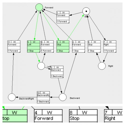
To test the software some LEDs had to act as motors. On the Arduino the software does what we have seen in the state machines above.
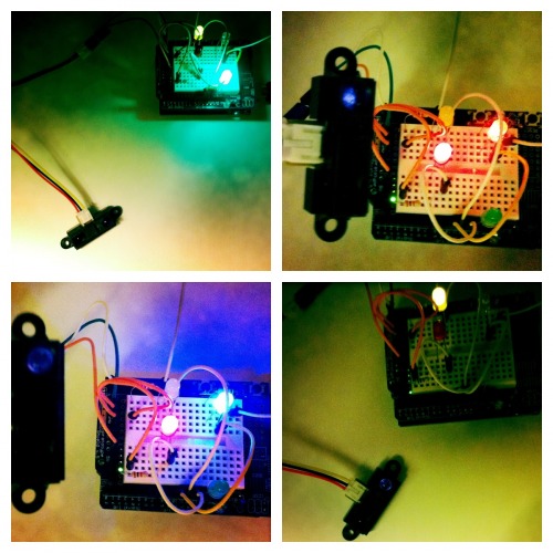
Yet Another Challenge Solved - The Drive.
Shure the drive is of a simple nature. But it is on a solid technology base modeled with the comprehensive meta-model of CIP. So its a small step for mankind but a giant leap for me.
10. Track Drive Software Integrationtest
Here is a first video of an integrationtest of the track drive software. It works all fine.
http://www.youtube.com/watch?v=SEJqkLGNPug
You can find the source code here: https://github.com/mnemonia/robotix/tree/master/Robots/Fhotibot
Software, Proximity Sensors and Gearmotors integrated - Challenge Solved.
After solving the using C++ code from C the Adafruit Motor C++ Library could be connected to the drive software and the LEDs were replaced by the real gearmotors. So from now on the Fhotibot can avoid obstacles. Field open for the next challenge.
11. Hierarchical Control System
For the next level of software the basic architecture relates to the Hierarchical Control System. Fhotibot's Drive is on one level, the Target-Finder is above. While the Target-Finder knows where the desired target is (the place where the noise is loudest) it knows nothing about how to drive a motor and not how to avoid obstacles. The drive knows how to do that and can command the robot if there is some obstacle in the way.
The Target-Finder and the Drive can each be deployed on a different microcontroller. This gives flexibility to the system and isolation of the building blocks. The communication can be wire or wireless. It is not desided yet.
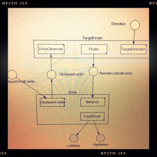
The drive itself knows how to avoid obstacles so the Clear/Attention/Danger state machine is in a low level of the system.
Also the sensors for obstacle avoidance are close to the drive and controlled by the same microcontroller.
12. Remote Control to simulate the direction
The noise finding is quite a challenge so the Fhotibot needs some alternative source of target finding. For now a remote control sinulates this so I can command the robot where the noise is but the robot finds the way by itself.
As a remote control the Fhotibot got a hacked remote control from a helicopter.
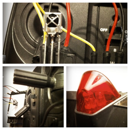
The infra red sensor is patched to the top of the body. The head is missing right now.
Yet another challenge solved: Software architecture fixed
The hierarchical system makes sense for the Fhotibot and helps to keep clean with the single responsability principle.
By now everything was simple and decomposed into a traditional layering with functional coherent finite state machines.
But now I rotated this vertical block of layers 90° had a left to right semantics instead top to bottom for the sensor actor path. The top down layering is now behavioral coherent. This was my move to start play with behaviors in a subsumption architecture style.
Left is the sensor, right or below is the actor. Above is highlevel behavior. Beneath is lowerlevel behavior. The layers are biderectional connected and interchange messages about state changes. We call these message Pulse A pulse in a pulscast net. That is the communication network between the state machines.
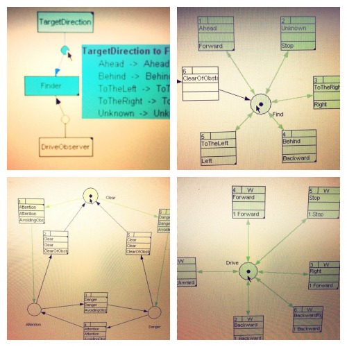
In the pulscast net you see the messages and mappings between the state machines, the processes.
The object avoidance with the states and transitions.
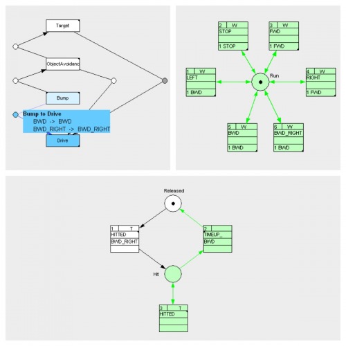
The bumper with the states and transitions. Here with a timer in the HITTED transition that lets the drive move in the direction backward-right and stay in the Hit state until the timer is up. It then goes to Released via TIMEUP_.
The C connector code sends a tick in every end of the Arduino loop to count the timer up.
By then it was time to change the discipline and move over to mecanical objectives.
Literature and own Brain
Yet another challenge solved. Software architecture style studied and applied on the Fhotibot. Reactiveness still high. Then the IR sensors where mounted. No bumpers yet.
14. Find out where to go. Use closed eyes
Since the Fhotibot once seeks where it is loud the robot needs a target finder strategy. The strategy compares a left- and a right-side analog value and determines, if the left or right is greater or if they are same. To test this some photoresistors had to act as closed eyes. With closed eyes you can see, if the light comes from the left or the right. For now this is a sufficient test setup to test the software and electronics.
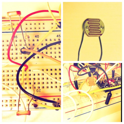
To test the the finder state machine once again a few leds showed what direction the robot would go.
So now the current software works. With the new Arduino Nano that goes into the head of Fhotibot a second microcontroller comes into play. The software does currently not support to run on two MCUs. But for testing that is sufficient.
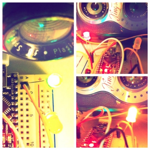
15. Electronics for the Head. Use closed eyes and ears
With the knowledge on how to combine behaviors the head got some sensors that allowed Anti-Moth and Home and Wander behavior. With the LDRs the Anti-Moth and with the microphones the Home. The challenge is still the sound bearing that is used for homing.
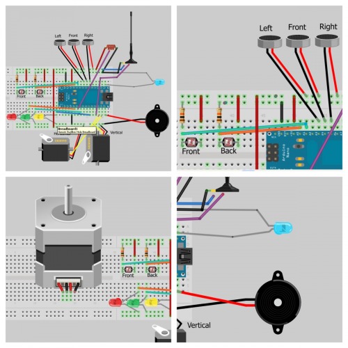
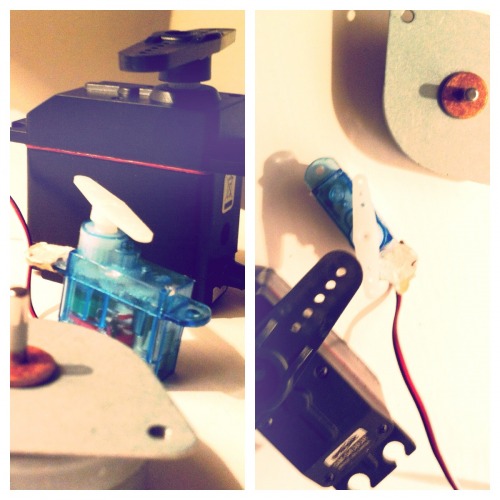
Since I have not desided yet, what camera should be used, I have a plan A and B. Plan A is to trigger a photo by using an digital HIGH signal. This is shown with the blue LED that indicates the DO to a camera DI. Or plan B is a mechanical solution with servo on a PWM pin that can click a release of a camera.
The stepper-motor is an option for the head rotation with gears. Greater gear screwed on the body and smaller gear with stepper-motor screwed to the head. That is most robust... but the only gears I have right now are inside an old Pioneer turntable. The greater gear is a bit too large. So maybe I order some norm gears from here that can do the job. This is my prefered solution.
The bi-directional communication between head and body carries the events triggered by the behaviors. The head sends i.e. for the Anti-Moth FWD, BWD, LEFT or RIGHT to the Drive. The body sends an NoObstacleAhead event to the head so the homing can continue.
Good for now. But each sensor must be mounted to the head camera...
...and that is what might come up next.
16. Head's up
The mechanical mounting of the head kep't my mind busy. It had to be solved. Soon. I thought about it enough. It's the quality attributes that really matter here. Who want's a head that always cracks and falls off, when a child plays with the robot? So robustness is key. But light, removable and crafted with material that have left their best time behind them.
3 Swiss Francs for an old vynil record player from the thrift store. The parts inside the player where ideal material for further use. Besides some buttons, sponges and screws there was the mount from the body to the rotating table. This mount is very solid and resilient.
Time to do some mechanix.
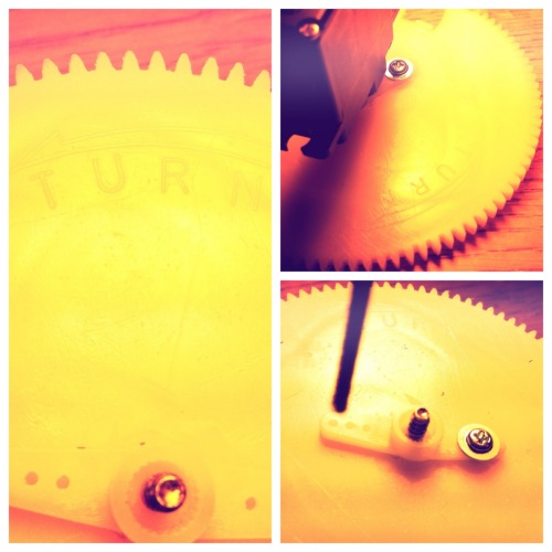
Now the head has a rotateable baseplate with the great gear. The gear is screwed to a servo.
To the Fhotibot this is now a neck. It can look in all 360° angles. This is because the servo is mounted to the great gear. A few degrees servo rotation leads to a lot of effective head rotation.
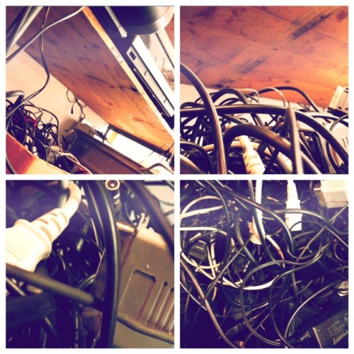
Where I found the Polaroid
Once I wrote as the introduction of the Polaroid "It was waiting for me hidden underneath a thick layer of cables in a box in a local thrift store." Here is where I found it.
16. Head rotates (new)
The mechanical mounting is finished and the servo mounted. Here is the concept of how I turn the head.
The servo is mounted to the grand gear.
Embedding the servo into the head. The gears must exact go into each other.
I'll keep updating this robot page until the project is finished...
Happy coding, Nils
Appendix A: Studied resources
http://www.ladyada.net/make/mshield/use.html
http://bildr.org/2011/03/various-proximity-sensors-arduino/
http://www.societyofrobots.com/sensors_sharpirrange.shtml
http://lists.freeculture.org/pipermail/list/2010-April/000899.html
http://www.arduino.cc/cgi-bin/yabb2/YaBB.pl?num=1295766321
http://www.techmoan.com/blog/2011/12/25/christmas-presents-the-80816-camera.html
http://www.picaxe.com/docs/picaxe_sound.pdf
http://www.actifsource.com/cip_tool/
http://www.arduino.cc/cgi-bin/yabb2/YaBB.pl?num=1271452409
https://www.robotshop.com/letsmakerobots/node/2755
https://www.robotshop.com/letsmakerobots/chill/view/133?page=1
http://www.arduino.cc/cgi-bin/yabb2/YaBB.pl?num=1273071024
http://www.arduino.cc/cgi-bin/yabb2/YaBB.pl?num=1240931603
http://www.adafruit.com/blog/2009/05/19/piezo-with-an-arduino-photoresistor/
http://www.arduino.cc/playground/Learning/SingleServoExample
"This tutorial explains how to control a servo from your computer using arduino."
https://www.robotshop.com/letsmakerobots/node/1512
"Work with 2 levels, one called "Attention", and one called "Danger"."
https://www.robotshop.com/letsmakerobots/node/28278
"This tutorial shows the use of timers and interrupts for Arduino boards."
http://www.arduino.cc/cgi-bin/yabb2/YaBB.pl?num=1279102180
"As part of a bigger project, I've written a simple event dispatching system.
Its purpose is to decouple code generating an event (e.g. after debouncing a pushbutton the program "declares" that a key has been pressed) from the code that implements a response to that event (e.g. toggle a led or switch to a different menu page). "
http://www.behaviorbasedprogramming.net/manual.html
"Behaviors. What follows is the current listing of all behaviors and their parameters, although this list is constantly being updated to make the robots more flexible and interesting."
https://www.robotshop.com/letsmakerobots/node/31697
"Rotates a head along a mathematical function"
Find where it is loud. Go there. Take pictures.
- Actuators / output devices: 224:1 Solarbotics GM3, micro-servos
- CPU: Arduino Nano 328, Arduino Uno R3
- Power source: 6 AA batteries for motors, one 9V battery for MCU
- Programming language: C
This is a companion discussion topic for the original entry at https://community.robotshop.com/robots/show/fhotibot
