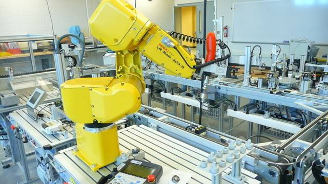
So I guess this counts as a robot project. Still haven't got much done on my own robots at home, so I figured I'd post about the robot at work. I'm a lab aide for Heartland Community College in their robotics, automation, machining, and electronics labs. We have a huge conference coming up so I've been redesigning the end effector on our Fanuc LR Mate. The purpose of the end effector is to screw in 4 screws on a part as it travels around an assembly line. It also has a gripper for other tasks that we may come up with later (thinking solving rubiks cube :) ).
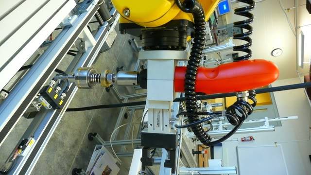
The company we bought the assembly line trainer from sent us an end effector that used a Black and Decker screwdriver. It seemed really cheap compared to the rest of the equipment, and we were having problems with power, tolerances, and torque control. You can see in this picture the set up, plus a torque driver that I made. The driver is a little over the top, but why not :)
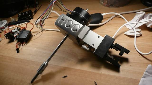
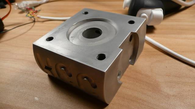
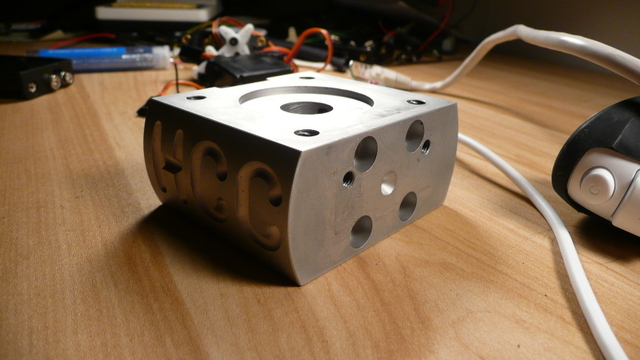
So now on to my new project. I decided to switch the Black and Decker out for a stepper motor. I've got the mounting base all finished up, as well as the screwdriver extension. Now I'm on to the electronics.
Next step is to build a stepper motor controller/driver that I can controller via the robot controller and use in programs. Does anyone have any plans for a beefy stepper motor controller that can controller on/off, forward/reverse, and stepping speed? I have a kit that was used in an electronics class, but I'm a little worried that it won't be built well enough to survive years of abuse by students.
Well that's it for now, I'll post some pics of the end effector mounted, and whatever I come up with for the controller. Cory
This is a companion discussion topic for the original entry at https://community.robotshop.com/robots/show/fanuc-end-effector
Torque
This link to a similar stepper shows it to only be capable of 36 oz-in torque. That is less than the RC servos pictured on the table, that only run 4.8 volts. If a power screwdriver makes use a gearbox to increase torque from a typically stronger brushed DC motor, then a similar or even higher ratio gearbox might be helpful in getting sufficient output from a weaker stepper motor.
By wire count, your motor appears to be unipolar, not bipolar. Bipolar steppers only have 4 wires. 5 or 6 wires is typically 2 coils with 1-2 center taps.
ahh yes unipolar, I always
ahh yes unipolar, I always get them mixed up. Like I said, haven’t played with steppers much.
the stepper in the link is very similar, but I think this ones much older. Who knows where it came from, I just found it in a box 
I could use a gearbox, but then I’m just adding more complications and things for students to break haha.
Is it possible that the driver I’m using is regulating current?
It’s very similar to this one http://www.electronickits.com/kit/complete/motor/ck1404.htm but from Jameco
Stepper driver
The driver board linked uses a UCN5804 stepper translator chip. The stepper is labeled a 12 volt 0.4 A stepper, so it can be calculated to have a 30 ohm coil resistance. The driver chip is rated to cover 1.25 A, (1.5 peak) so it probably isn’t the limiting factor. The outputs will have the BJT loss of Vce-sat which is 1.0-1.2 volts at the current level expected. So one minor possible limit might be in a regulated 12 volt supply losing 1.0-1.2 volts to deliver less to the stepper, only 10.8 to 11 volts, lessening the current used across a 30 ohm coil. A more likely limit might be the power supply used and whether it can reliably deliver 400 mA.
But all this ignores the idea that steppers are pretty weak their own, and can only do so much. 12 volts x 0.4 A is only 4.8 watts, and nothing is 100% efficient.


