

ezLCDuino.pde (1616Bytes)
Custom_Controller_V2.pde (2629Bytes)
ezLCDuino_Simple_Demo.pde (233Bytes)
I am just going to make it clear that the boards are not currently going to come preprogrammed with some kind of serial LCD backpack code or other code. It will be up to you to program it how you please, but all the capabilities are there. I will be posting example code though and hopefully some tutorials to get started.
Price is $20 for a full kit without a LCD and $25 for a full kit WITH a 16x2 LCD. (plus $5 shipping in the USA). A kit consists of everything you will need to assemble which includes a PCB, caps, resistors, transistor, resonator, trim pot, IC socket, Atmega 328 with Arduino Bootloader, and 40 breakaway male headers. Like I said before, for an extra $5 ($25 total) you get a LCD too. It is a white on blue LCD.
Update 07.15.11
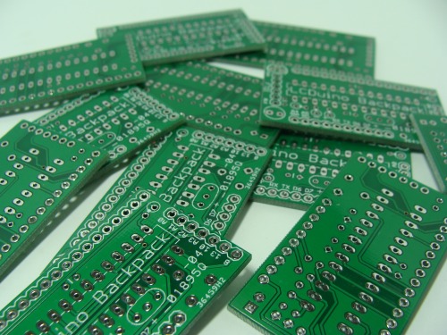
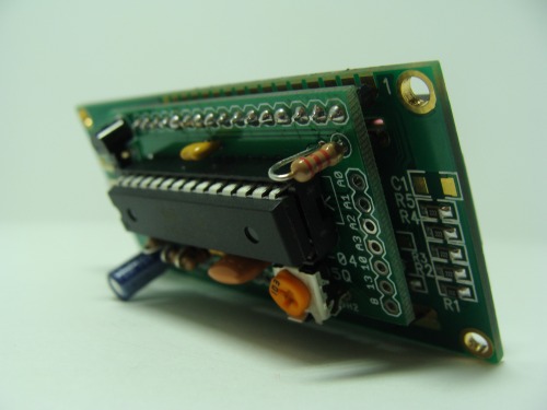
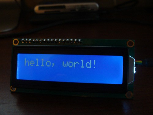
Well the PCB are here and I have assembled and tested one.
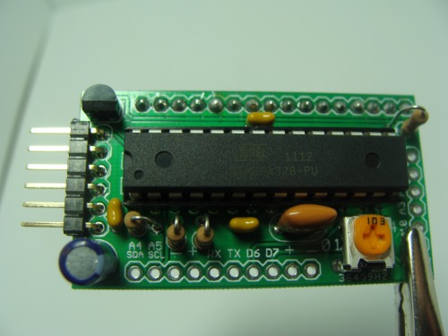
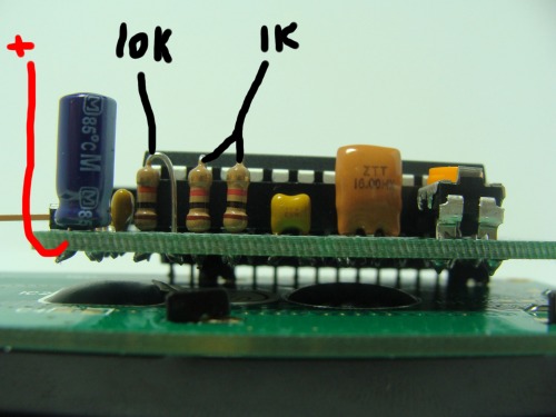
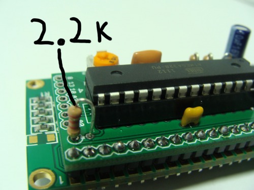
Some labeled resistors and notice the polarity of the electrolytic cap. The sqaure pad is positive, that is the one on the left in the photo below.
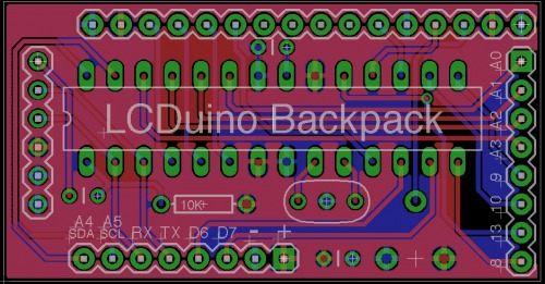
V1.2
There are resistors on the UART pins to allow users to program the Arduino without unplugging what they have connected the TX and RX lines. There is an added 10uf cap. A transistor allows the backlight to be turned on and off or PWMed from pin 9.
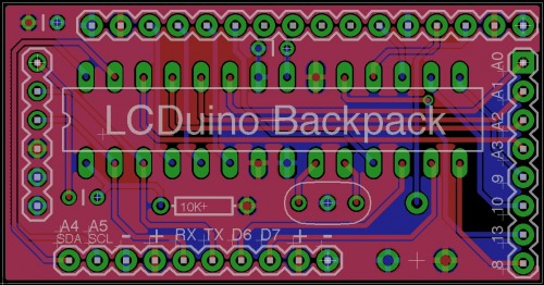
V1.1
Added more power connections on the communication row so the board can be interfaced to using a 4 or 3 pin cable depending on if you are using I2C or using serial with just RX or with TX as well.
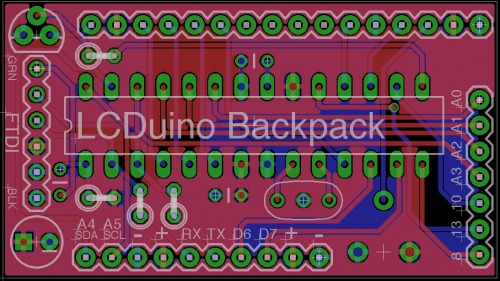
V1.0
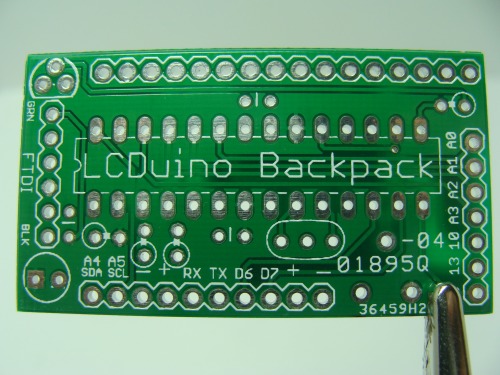
This is my ezLCDuino Backpack. It is an Arduino LCD backpack. This will solder on directly onto the back of a LCD allowing you to control it using the Arduino LCD library.
Features:
- FTDI programming port
- I2C communication pins
- Serial communication pins (hardware and software)
- Trim pot for adjusting the LCD contrast
- Arduino Atmega 328
- 4 spare Analog pins (not including the ones used for I2C communication)
- 3 spare digital pins (not including the ones used for serial communication)
- PWM control of the backlight
- Resistors allow the Arduino to be programmed without unplugging devices connected to the TX and RX pins
On the bottom of the board is what I call the "communication row". Here are I2C pins, hardware serial pins, and 2 digital pins you can use for software serial. Down here is also where you power the board. The pins you do not use for communication can be used for a different purpose of your choose. I suggest Bill Porter's serial library for communication.
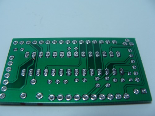
On the side of the board are the left over pins. This gives a total of 7 digital pins and 6 analog pins on the board excluding the LCD connection at the top.
So use the board as a serial or I2C LCD backpack, use it as the main microcontroller in your project that contains a LCD, or use it as a slave to control the LCD in your project and provide extra pins and processing power.
I will order some PCBs this week and get them in people's hands soon. Tell me what you think.
https://www.youtube.com/watch?v=VmJiAG6ma1g