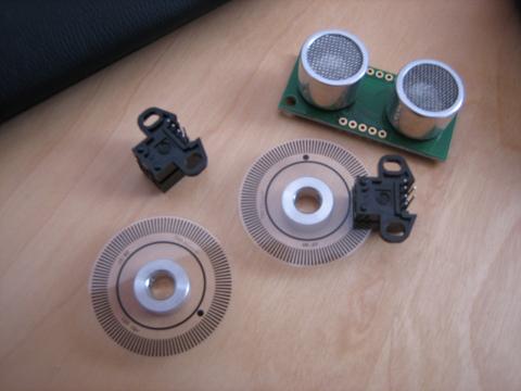
[Need help with Hardware (Encoders), see last Picture]
Hi There, although I just registred, I've been visiting this Site for a while. Now that I started my own robot, I thought it was a good Idea to share it with you.
The future "Brain" will be an Atmel but I am not shure wich one. Right now I am using an 8515, but i Think I'll eventually have to go for an atmega32 or something like that.
Although I know you all got some great working and funky looking wheelbases and chassis, I decidet to buy an RC-Tank and go with that.
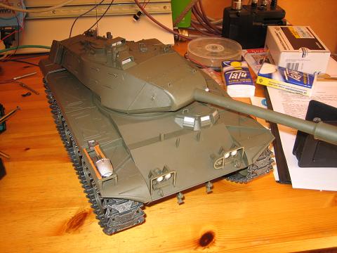
After getting rid of all the crappy electronics that came with it, it pretty much looked like in the Main-Picture above.
Then I made a cartbord mock up of the top I am going to build. Later on it's going to be made of thin sheet metal.
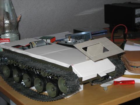
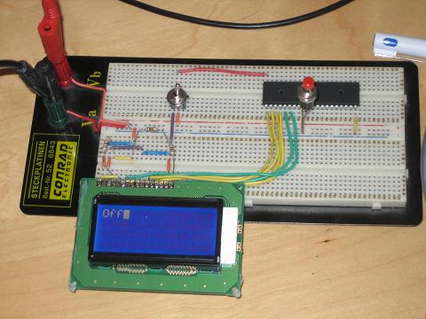
The wohle in the front will fit this 16x4 Display:
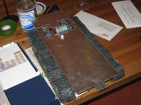
I've started on making a metal top, but I didn't get very far yet, here is what it looks like right now:
My drive Unit right now consists of an ATiny 2313 that gets speed and direction data via SPI-Interface. It then sends direction and PWM to a l298-Motor driver.
It will controll the speed with two rotary encoders from Sharp. Here's a picture of how far i've got so far:
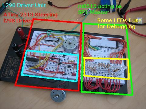
Hope you like it so far. Once I get the encoders working too, I will transfer this on a PCB, but I don't want to do it yet, because custom PCBs are expensive^^
Ahh, finally my parts arrived, but apart from being a challenge as far as programming goes, i don't know how I am going to mount my encoders on my motors. Any Ideas? Please comment.
- Control method: Autonomus/RC
- CPU: ATiny 2313
- Power source: 5V DC
- Programming language: Assembler
- Target environment: indoor
This is a companion discussion topic for the original entry at https://community.robotshop.com/robots/show/explorer-1


