I like to show an example on how to handle Torque control of a Brushless Motor with Hall Sensors using Arduino UNO, a Brushless DC Motor with the part number of “DB56C036030-A” and Solo UNO as motor controller.
To make it work, I also use the Library for communication between Arduino and Solo here .
The idea of this example is to lock the shaft of the motor by hand and by code increase the torque of the motor gradually in order to feel how the force is increasing every time.
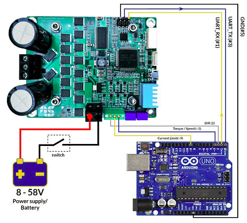
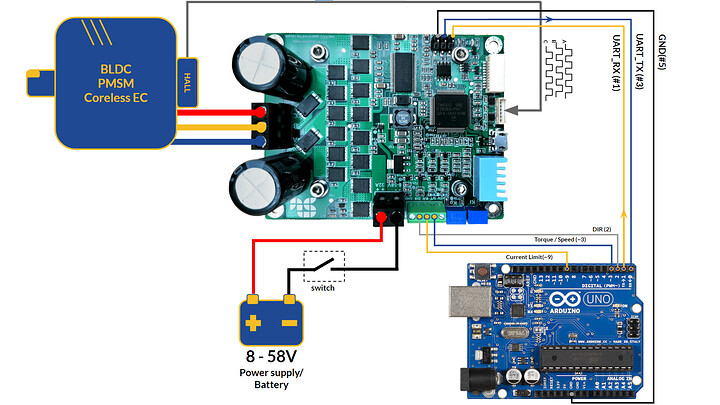
The schematic is here:
- The piano switch for Solo UNO is from pin 1 to 5: Down, Up, Up, Up, Down.
- the pin “~3” of Arduino UNO is connected to “S/T” input of SOLO, which in our configuration will define the Torque reference, this reference is calculated based on the maximum current that SOLO can feed into the Motor.
- pin “~9” of Arduino in which will define for SOLO the current limit and it’s connected to “P/F” input of SOLO for protection purposes.
- correctly calibrated the Hall sensors windings to ABC outputs of Solo
And this is the code:
#include <SOLOMotorController.h>

#define AnalogueCommandMode 0
#define PMSM_BLDC_Normal 1
#define UsingHallSensors 2
#define DigitalCommandMode 1
#define ControlType_Torque 1
#define ControlType_Speed 0

//instanciate a SOLO object:
SOLOMotorController *SOLO_Obj1;

//the device address of SOLO:
unsigned char SOLO_address1=0;

//Desired Switching or PWM Frequency at Output
long pwmFrequency=16;

//Motor's Number of Poles
long numberOfPoles = 8;

// Current Limit of the Motor
float currentLimit= 12.5;

// Define Desired Torque referrrence
float desiredTorque_Iq = 1.5;

// Converted value to PWM duty cycle for Iq
int desiredDutyCycle_Iq = 0;

// Converted value to PWM duty cycle for currentLimit
int desiredDutyCycle_CurrentLimit = 0;

// Define the Max Measurable current in SOLO UNO for 100% duty Cycle
float MaxMeasurableCurrent_SOLO_UNO = 32.0;

// Battery or Bus Voltage
float busVoltage = 0;

// Desired Speed Limit[RPM]
long desiredSpeedLimit =3000;

// Motor speed feedback
long actualMotorSpeed = 0;

// Motor Iq (torque) feedback
float actualMotorTorque_Iq = 0;

void setup() {

  Serial.begin(115200);

  SOLO_Obj1 = new SOLOMotorController(SOLO_address1);
  delay(2000);

  busVoltage = SOLO_Obj1->GetBusVoltage();
  while(busVoltage <=0){
      busVoltage = SOLO_Obj1->GetBusVoltage();
      //wait here till communication is established
      Serial.println("\n Trying to Connect To SOLO");
      delay(1000);
      }

  Serial.println("\n Communication Established succuessfully!");

  //dummy read after Serial.println to open the UART line
  SOLO_Obj1->GetBusVoltage();
  // Initial Configurations
  SOLO_Obj1->SetPWMFrequency(pwmFrequency);
  SOLO_Obj1->SetCurrentLimit(currentLimit);

  //select Digital Mode
  SOLO_Obj1->SetCommandMode(DigitalCommandMode);
  SOLO_Obj1->SetMotorType(PMSM_BLDC_Normal);

  //Operate while using Hall sensors
  SOLO_Obj1->SetSpeedControlMode(UsingHallSensors);

  //run the motor identification
  //run ID. always after selecting the Motor Type!
  SOLO_Obj1->SetIdentification(true);

  Serial.println("\n Identifying the Motor");
  //wait at least for 2sec till ID. is done
  delay(2000);

  //dummy read after Serial.println to open the UART line
  SOLO_Obj1->GetBusVoltage();

  //Go back to Analogue Mode to accept PWM as Reference for Torque and Speed
  SOLO_Obj1->SetCommandMode(AnalogueCommandMode);
  //Enable PWM pins of Arduiono with Fixed frequency greater than 5kHz

  pinMode(3, OUTPUT); //torque adjuster connected to "S/T" on SOLO UNO
  pinMode(9, OUTPUT);//current Limit adjuster connected to "P/F" on SOLO UNO

  pinMode(2,OUTPUT); //Direction Control Pin

  // declare pin 3 to be a PWM enabled output with 31kHz of fixed Frequency
  TCCR2B = TCCR2B & 0b11111000 | 0x01;
  // declare pin 9 to be a PWM enabled output 31kHz of fixed Frequency
  TCCR1B = TCCR1B & 0b11111000 | 0x01;
}

void loop() {

  // Converted value to PWM duty cycle for desired current Limit on 8 bit PWM of Arduino
  desiredDutyCycle_CurrentLimit = (int)(255 - (255*( currentLimit/ MaxMeasurableCurrent_SOLO_UNO)));
  //Set the right Duty cycle on Pin ~9 for current Limit
  analogWrite(9, desiredDutyCycle_CurrentLimit);

  //Define the desired torque in Amps
  desiredTorque_Iq = 1.5;

  //Define the Direction of Rotation
  digitalWrite(2,LOW);

  // Converted value to PWM duty cycle for desired Iq on 8 bit PWM of Arduino
  desiredDutyCycle_Iq = (int)(255*(desiredTorque_Iq / MaxMeasurableCurrent_SOLO_UNO));

  //Set the right Duty cycle on Pin ~3 for Torque
  analogWrite(3, desiredDutyCycle_Iq);

  // wait till motor reaches to the reference
  delay(500);

  actualMotorTorque_Iq= SOLO_Obj1->GetQuadratureCurrent();
  Serial.println("\n Torque (Iq): ");
  Serial.print(actualMotorTorque_Iq , 7);

  //dummy read after Serial.println to open the UART line
  SOLO_Obj1->GetBusVoltage();


 // wait for user to read
  delay(3000);

  //Define the desired torque in Amps
  desiredTorque_Iq = 2.5;

  //Define the Direction of Rotation
  digitalWrite(2,HIGH);

  // Converted value to PWM duty cycle for desired Iq on 8 bit PWM of Arduino
  desiredDutyCycle_Iq = (int)(255*(desiredTorque_Iq / MaxMeasurableCurrent_SOLO_UNO));

  //Set the right Duty cycle on Pin ~3 for Torque
  analogWrite(3, desiredDutyCycle_Iq);

  // wait till motor reaches to the reference
  delay(500);

  actualMotorTorque_Iq= SOLO_Obj1->GetQuadratureCurrent();
  Serial.println("\n Torque (Iq): ");
  Serial.print(actualMotorTorque_Iq , 7);

  //dummy read after Serial.println to open the UART line
  SOLO_Obj1->GetBusVoltage();

  // wait for user to read
  delay(3000);

}
So the thing that is happening is, in the code is hardcoded desired torque in Amps, then it will convert it to a PWM duty cycle on pin “~3” for each reference, the PWM duty cycle will remain constant as long as the reference has not been changed. In Arduino UNO, the PWM section has a 8 bits counter and this means to go from 0% to 100% duty cycle we have 255 steps, which will define the resolution of Torque control, the frequency of PWM pulses is not important and anything above 5kHz it’s ok, both pin ~3 and ~9 are on 31kHz.


