Hi to all.
I have been creating a range of alternative modular gippers for my
Lynxmotion AL5D PLTW and will be posting details when complete,
It has the ‘Lynxmotion SSC-32U Servo Controller Board’
I am working on an electromagnet head now and wondered if I can connect this electromagnet direct to the board, and if so where.
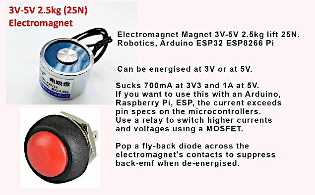
any help appreciated. It just needs on and off function.
thanks in advance
Roy
@roy_cooper Looking forward to seeing what you’ve created! It seems like the electromagnet is simply a two-wire On/Off? If so, it’s best to use an external relay (as their description indicates). Since you’re using the SSC-32U, it’s best to use a relay board with RC input, for example:
https://www.robotshop.com/en/pololu-rc-switch-relay.html
https://www.robotshop.com/en/dimension-engineering-picoswitch-radio-controlled-relay---de-03.html
You’d connect the input to the relay as you would a standard servo (to one of the SSC-32U’s servo pins). You can use a separate power supply for the electromagnet or use a regulator. this is because normally the power supply included with the AL5D is 6V, and this device seems to max out at 5V, so you’ll need a separate 3V to 5V power source (batteries or wall adapter) connected to the relay’s Vin. Alternatively, you can split the VS from the SSC-32U to a 5V regulator which then goes to the Vin of the relay. If you’re not 100% certain of the connections, feel free to sketch it for feedback here, then provide clear photos of the setup before applying power to confirm.
thanks for your prompt reply and I shall study your suggestions.
I will show my others when finished
thanks
Roy
continuing with this peoject. and help appreciated.
I will be using a 5v 1 amp power supply to supply a 5v 1amp electromagnet.
I want to put a 5v led single bulb in line to indicate when power is going to the electromagnet.
do I need to add a resistor in line and if so, what size resister please.
many thanks
Roy
Hello @roy_cooper,
Nice project! I’m looking forward to seeing how it turns out 
To select the resistor in series you need to know the LED’s specifications (forward voltage and max current).
Then you can use this equation to calculate the desired resistor value:
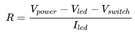
Vled is the LED forward voltage drop across the LED in volts. Typically, the forward voltage of an LED is between 1.8 and 3.3 volts. It varies by the color of the LED. A red LED typically drops around 1.7 to 2 volts, a blue LED may drop around 3 to 3.3 volts.
Thank you so much for your answer. I have tried to come to terms with your equation, but a 71 years old, its hard to learn new things, lol.
I have over 10 finished grips now and this is the last, so not long now,
perhaps with the details of the parts I have purchased you can help some more.
maybe the parts are wrong…
thanks Roy,
As I said, I am using a 5v 1amp power supply…
Ive spoken to the supplier of the lcd and they have told me that the lcd has a built in resistor that will be right for the job,
so I will try it and see,
thanks again for your help
Roy
That’s great.
Althought keep in mind that the nominal voltage for the LED is 12V so a 5V power supply won’t be enough.
Thanks again Geraldine.
It is a 5v lcd I purchased, however after 3d printing the parts I found that having the lcd made it harder to assemble. (size restrictions and wiring etc).
So I am redoing it now without the lcd and its so much easier lol, and after trying it out, the lcd really didnt add to the benefits.
quite often I redo and 3d print a design many many times before I am happy with it.
I will be making a video asap to showcase the 15 plus grips that I have designed and made. Lets hope that others like them as well
all the best
Roy


