Hi everyone,
I am quite of a newbie in electronic but I learn quickly, here is my project:
I have a small amplifier wich is commended by a potentiometer. For some reason I would like to duplicate this potentiometer with a sonar (such as this). The potentiometer is a B50K (as this one apparently) so that if you turn it completly counterclockwise it switches the amplifier off. It's a logarithmic potentiometer I think.
-First, the idea is that I could use the sonar or the normal potentiometer equivalently (parallel assembly?)
-Secondly, I think I'd set a small switch (wich one?) that makes the sonar inactive so that the device is commanded with the normal potentiometer only.
-Finally, the way I would like the sonar to work is as follow: if you pass your hand just above it (at around 5cm) it acts as a switch (on/off), but if you putt your hand higher (from 20 to 60cm) you can adjust the volume by moving your hand verticaly.
The main question is what PLC (picaxe I guess) do I need? I'll upload a diagram of how I plan to make it soon, if anyone want to drop an eye on it... :)
Thank you in advance.
The way I see your project
you should be able to easily do what you want with a 08M PICAXE. You should/could also add a digital pot. From there connect both the pot and the sonar to 08M inputs and the digital pot to an output. As you would be using the digital pot for actual control, its specific resistance would be less important. If you require a switch to select one or the other just make sure that it will let you select one of 3 positions and disable the power to the option you don’t want to use.
After looking at the sonar you selected, you may want to consider something more in line with the typical 5v digital logic supply. I would suggest something from here.
These are just my suggestions as I see your project.
Hello birdmun, thank you for
Hello birdmun, thank you for your great help, do you think I can use this controller for the 08M PICAXE? I am not sure because it seems like it has 3 outputs and 1 input. Please correct me if I am wrong: in the 08M PICAXE we will have 2 inputs 5VDC, 1 input for the sonar, chips for serial, one output to the digital pot, concerning the existing pot, I would say only one input (although it is a 6pins stereo logarithmic potentiometer) Than in the digital pot, we will have one input coming from the 08M PICAXE, 2 (stereo) inputs from the source and two outputs back to the amplifier, and chips for serial of course. Is that correct, more or less? And concerning the switch I thought of a normal switch only connected to the sonar so that I am always allowed to use the B50K (I only need to be able to switch off the sonar). And one more (stupid) question: does the sound interact with the sonar? It’s for an amplifier and the sonar works with ultrasound…
Thank you for your time and sorry if I ask useless questions.
I’m just shooting from the hip(ie kinda guessing)
I would not promise any of my concepts will work.
That said, the 08m has serial tx/dx, which could talk to the digital pot. The 08m also has 3 more pins that can be analog or digital inputs or digitial outputs. And, finally, it has another pin that can be a digital input. Counting those up, the serial for the pot, single I/O for the sonar, single analog input for the pot (for a typical pot, you tie one side high, the other side low, and the center to the analog input). The 2 source pins confuse me. I don’t know what you mean for sure.
And, for the ‘stupid’ question, my answer is a noncommital, “I don’t know.”  I would guess, that as ultrasonics work in the 40kHz range that audio should not affect the functioning of the sonar.
Re: the controller board
The board you linked to is really meant for powering servos at 6v, Rather than install an actual voltage regulator they just pull the 6v to the servo connectors and then use a diode to step down the 6v to about 5.3v for the PICAXE. You don’t really need a prefabbed board for this, if it works as I think it should. You would need a 5v regulator and the ability to make your connections to your external parts. In my opinion you would be better learning a bit of the electronic concepts and then constructing a board for yourself, even if it is just a point to point wired mess on teh back side of some perfboard. Although as simple as I am guessing the circuit is you might be able to get some help with the circuit layout and maybe find someone willing to fab a board for you. A hackerspace might be a good place to look if you have any near you.
hello birdmun, thank you
hello birdmun, thank you again for your usefull advices.
Talking about the 2 confusing source plug, apparently I was correcting this mistake while you wrote your answer I found some stereo audio amplifier with digital control project here. As the diagram looks similar at some points, I took the DS1868 digital pot that was used there in my model. I made a raw diagram if you want to drop an eye: (I can make it cleaner if you need)
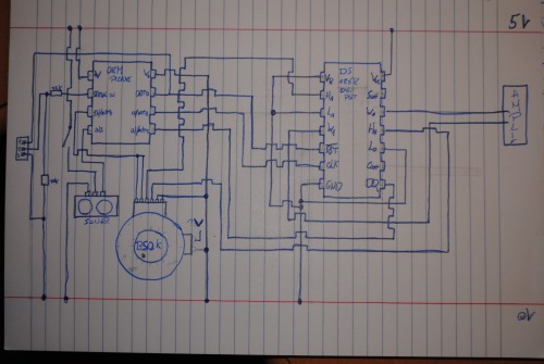
(The RST, CLK and DQ are the Serial Port Reset Input, Serial Port Clock Input and Serial Port Data Input respectivly)
The main question now is about the existing pot. It has 6+2 pins, the 2 extras are for power supply I guess (it can act as a switch), the 6 other are divided as this: 2 to ground, 2 inputs and 2 outputs (R and L channel). The 2 inputs are the source for me, the source we will "amplify" with the digital pot (connected to H1 and H0 in the creepy diagram). But can I let it connected to the B50K? Because by doing so, if I decide to set the volume lower with the sonar, the B50K will still amplify it right? But in another hand if I disconnect it the B50K will have nothing to amplify and will not be able to send a "message" to the 08M PICAXE... Or maybe it can use some power from the 2 extra pins... Am I still clear? Oô
Thank you again for your help.
PS: The digital potentiometer I used above is the DS1868.
One issue I didn’t realize
SPI is not available in hardware on the 08M. Look at this blog. The blogger shows how he(?) used an 08M with SPI.
You will need to move to a larger PICAXE. The 08m does not have enough control pins to do what you need to do. If you were using an 8 pin PIC, you might be able to get away with it, but, that would require learning a different language and a different programmer.
The idea is you have two input choices, sonar or pot. You then use the PICAXE to talk to the digital pot to make the adjustments based on the input that the PICAXE receives from one of the two inputs. This is the other reason I don’t really believe something like the B50K is required. You are welcome to try using it and if you want discreet control over separate channels you will need to connect the L and R wipers to individual analog pins.
I can’t seem to find a datasheet on the B50K pot, but, I don’t believe there should be any direct connection between the pot and the digital pot, barring a shared ground. The PICAXE should be the only thing controlling the digital pot. The digital pot pins that you are connecting the B50K to, H0 and H1, really need to be connected to your audio source, if I understand things correctly.
Have I lost you yet?
Aright aright, you didn’t
Aright aright, you didn’t completly lost me
I realise I made a couple of mistakes in the diagram. I’ll make another one -a bit cleaner- today, using the digital pot you told me first.
Hello birdmun,I made a new
Hello birdmun,
I made a new diagram. I used the digital pot you told me, or the one just above actually. I think that if I use the MCP41xxx I will have only one input to the digital potentiometer, and one output. I prefer to have two inputs and two outputs. I don’t need to control them independently (set one channel higher than the other one) but I think that if I connect the two channels to only one input and than I get only one output back (that I will have to divide in two back to the amplifier), I will get a mono amplifier in stead of the stereo it is. Amplifying independently keeps the stereo function. What do you think? Notice that I connect the output of the B50K together because I only need a single signal as input in the 08M PICAXE. I will use the Double Channel B50K just because I allready have it although I could use a single channel pot as you said 
So here is the new diagram:
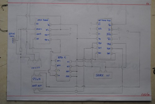
PSWA means Power Supply for the Whole Amplifier (the 2 extra pins of the B50K -Si and So on the diagram- act as a switch I think)
As you see I cleared a bit the situation with the B50K. I also discovered a new input to the 08M PICAXE, it's send by the "switch" of the B50K. The main question now is what goes where? I think I only need two outputs out of the 08M PICAXE: one that sends ON/OFF messages (this one should go to SHDN right?), and anotherone that sends values for the digital potentiometer. They both go to the Digital pot. Than out of this Digital pot I will have the amplified signal (PW1 and PW0) but I think I should also have something to connect to the PSWA to be able to switch it on (or off). What do you think of this diagram?
Once again, thank you for your time
May I just say WTF
The WTF is for the suggestions in the comments.
All you need to get a variable resistance out of a voltage or current output such as the one from the sonar is a tranzistor.
It’s in the name!
And if you just put a switch in series with the tranzistor it will be just like removing it from the circuit.
Hello antonio, your comment
Hello antonio, your comment makes sense: now I know what a transistor is for
But even if my diagram might not be correct yet (and I know I will certainly fight to death with the code lines) I think I’ll keep trying with the PLC and stuffs. It gives me more options (like using normal pot and sonar/ turn the amplifier on/off by passing my hand just above the sonar) in addition to that, it also gives me a good opportunity to start electronic and play around… Or maybe my patience will simply run out and I will burn the whole thing. Than I will consider the rational way
But let’s have a look at the tranzistor theory anyway: I just need to connect the sonar to the correct tranzistor in which I already connected the source, than from the tranzistor back to the amplifier. All of this in parallel to the normal pot and I have a switch at the source of it so that I choose to use sonar or normal pot. I am certainly wrong somewhere as usual but that looks insultingly simple already
Thank you for your help anyway. Not using it right now does’nt mean it was useless. And congrats for your gap passing robot by the way.
Cheers
Well…
I’m sorry if I came on too strong, I also like to do things just so I can learn more.
You definately got the right idea about how to use the tranzistor.
You could also have the potentiometer in series with the tranzistor. This way the total resistance is the sum of the pot + tranzistor. You can set it up so that when you put your hand really close to the sensor you get “infinite” rezistance from the tranzistor - which should cut out the volume completly, regardless of the position of the pot.
I agree that a microcontroler is far more flexible, because you can process the sensor inputs using all kinds of funky logic, but you then have to get your output back into the analog world and that’s a bit more complicated.
final diagram
Hi everyone, I think this time I’ve got it right,
I finally choose a 14M PICAXE in stead of the 08M PICAXE because as birdmun said, I need more than 8 pins. I connect the PLC to the digital pot as they did in the blog birdmun gave me.
@Birdmun: Do you think the 14M PICAXE and the code lines on the blog mentionned above will solve the missing SPI problem?
@Antonio: You say it will be complicated to go back to the analog world but isn’t it the job of the digital potentiometer? Although I will need to read the MCP42XXX manual
I really think this is the right diagram, so if anyone want to drop an eye on it… Because I think I am going to order the components and a stripboard
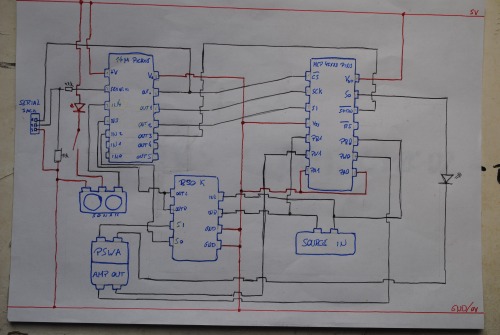
Well let's say "source in" is source out actually: the source we will have to amplify. And "Amp out" is Amp in: these two pins go back to the amplifier, bringing the amplified signal.
Thank you for your advices and opinions
At a guess
What works on a 08M should work on the 14M.


 I would guess, that as ultrasonics work in the 40kHz range that audio should not affect the functioning of the sonar.


