Welp drumbot was interesting, I got him to the point where he could approach, align, and drum on objects, but shortly thereaftrer the gears stripped on one of his GM10 stick motors when the stick got stuck on something. *sigh* In any case, DrumBot is finished, and his components are now being reclaimed for a rebuild of igor :-). Pics of that coming soon-ish.
------------------------------------
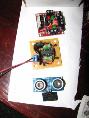
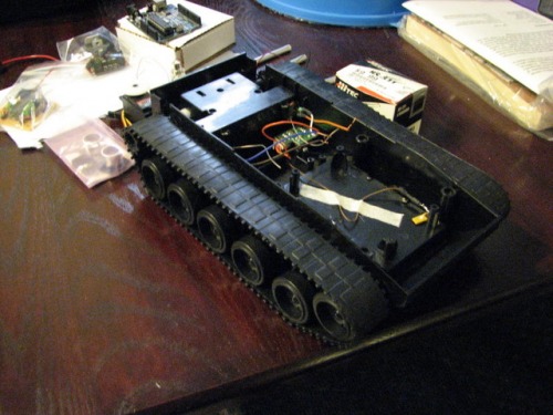
This is the makings of my drumming robot. I know, I know, it's been done again and again, but hey I guess Fritsl started a craze :-) Anywho, I am using a stripped down toy tank chassis as the base, an Arduino for the brains, a solarbotics L298 board to drive the tread motors and a custom SN754410 board I made to control the sticks, which are very much like the ones from LDM, GM10's with 1/4" aluminum tubing. For the sonar, I am using a parallax PING. I am still figuring out exactly how I want it to go together, but this is the basic bits of it....
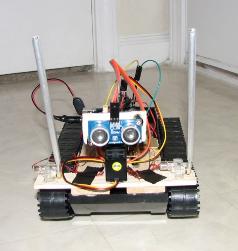
I got some time in with the glue gun today, and got DrumBot mostly assembled. I wrote a quick test program to test out my wiring, and the servo, the PING, and the 2 drumsticks work great. The drive motors work, however the arduino resets if I engage the both at once. I suppose I will have to have a secondary motor power pack or something after all :-/
Anyways, once I work that out, Drumbot will be ready to roll, or maybe it's ROCK N' ROLL :-)
So indeed he is underpowered, there is apparently quite a voltage drop due to the L298. I will have to pick up a small maybe 2xAA holder and piggy-back it with the other batteries
Drum on stuff
Actuators / output devices: Toy Tank chassis, HS-422 Servo, 2xGM10
There are a few examples here on LMR : for the Little Drum Machine of TheCowGod there is a couple pics of his 754410 layout, same pins. There is the tutorial by guibot that does not seperate the chip supply and motor supply. The datasheet gives the pins, Vcc1 to be usually a 5 volt supply, Vcc2 to be whatever the motors need (to a limit) pins 1,2EN and 3,4EN to be tied to +5 volts to enable the sides to operate, and pins 1A 2A 3A 4A to be controlled by your micro to drive one motor on 1Y and 2Y, with the other motor on 3Y and 4Y. Is there some specific prob you are running into?
Well gathering the Well gathering the materials, like inputs, transistors, etc… I am not sure cuz Ive only made two PCBs in my life and both were extremely minute (2 resistors 1 LED) etc, so I want to know If i am supposed to connect one of the outputs to the Chip, which leg, etc, Is it any different from the Arduino to Picaxe?
Just the small PCB, like was shown above and here. A socket for the chip is a good idea, and use of headers or screw terminals (better) to connect the device is good. The L293D inputs labeled 1A 2A 3A and 4 A go directly to your micro (PICAxe or Arduino or whatever). The Outputs 1Y 2Y go to one motor, 3Y 4Y to another motor. The Enables 1,2EN and 3,4EN can be wired directly to +5 volts (I used a resistor in the picture, probably not needed). The Vcc1 goes to +5 volts, (probably can go to higher values) and the Vcc2 goes to your motors power supply. Ground is the negative side (of both supplies if 2 are used.
wow thanks mate, I think Ill use header pins since I have so many jumpers
Wait how does that make sense though, the first part where you stated that 1A,2A,3A,and 4a go to the Micro Controller, which port on the MC, and why do some people alternate between the screw terminals and header pins, in the same board, just like buhatkj did
And thru this way, you say only 1y and 2y and 3 y and 4y, does that mean only two motors may be controllered per BoarD?
Yea I bought this and one 16 Yea I bought this and one 16 pin DIP, guess I need another then, I am pretty sure Fritsl used one though (one chip for the 4 GM10s)
Screw terminals and headers I think buhatkj chose very well in this robot, on his h-bridge. Screw terminals all around allow an easy hook-up. The motor outputs are ones that might require a little extra current carrying capability, so screw terminals make good sense there on the 1Y 2Y etc. I personally prefer header pins on the inputs, the 1A 2A etc, but ease of connection is good too with the smaller screw terminals.
actually the screw terminals are connected only to motor outputs and ground for each half-h-bridge. The inputs are connected to header pins; you can see them around the perimeter of the board…
power input is the large blue screw terminal at the top, with a 7805 regulator for logic power. My intent is to run the whole shebang off of 6xAA that will fit in the original battery box built into the toy tank. That should give me 9v, which should work fine for the arduino, motors and driver boards…
well the main reason for the spacing being the way it is, is so that the sticks will not interfere with the sonar panning. With this spacing they allow plenty of room for the sonar head to move through at least a 60deg arc, perhaps even 90deg, without the sticks getting in the way. you are correct though, that this means that the object to be drummed on must be at least as wide as that spacing, which rules out stuff like coke bottles…
I may improve the situation by canting the sticks inward, so that their path of travel would make an A sort of. that is something to consider, but I’ll have to see first if this is an issue at all.
It’s interesting having screw terminals to ground, do they help in some way? I see the header pins now, had just been counting screw terminals before, guessing they were alternating inputs and outputs.
Good idea on running a single supply to the board. I’ve done similar on another board, but used just a TO-92 regulator since the chip wouldn’t use much current.
Really cool video! Good to see Drumbot in operation. Looks like this one is gonna be loud! Maybe a wall of coke bottle! Oh, coke bottles with different levels of water in, to play xylophone on!
An H-bridge is only needed if you need to be able to drive a motor in both directions. If you only need to turn the motor on or off in one direction, you can use a transistor (or a relay, depending on the situation). The GM10s have a spring to return them to neutral position, so for drumsticks, all you need is a transistor. You turn the transistor on to send power to the motor when you want to hit something with the stick, and then you turn the transistor off to cut power to the motor when you want let the spring bring the stick back. The only place where Frits and I used an H-bridge chip was for controlling the GM-10 that was moving the SRF05, because it needs to be able to turn both left and right. (I eventually got rid of that GM-10 and used a servo to move my SRF05 instead, so I don’t have any H-bridge chips on my LDM anymore).
Looks good. I like that tank base. I used the Tamiya tracks on my BullyBot to get more of a tank-like appearance, but now that I finally got the motors working, I find that when the robot turns, the treads fall off. So I guess I still haven’t found a good set of treads for a tank-like robot. Yours looks good, that’s basically what I want to end up with.