If you are running out of input/output pins of your Picaxe here's something that might help you: Picaxe's configurable input/output pins can be used in three different states so instead of two output states (high/low) you can get three states (high/low/"tri-state" or hi-z). The third state is set by configuring the pin you are using as an input. When configured as an input the pin will have high impedance. That state is called "tri-state" or hi-z.
Having a high impedance means that the pin is "invisible" to the rest of the circuit or putting it another way around: High impedance pin does not affect the rest of the circuit at all. To use hi-z state of a pin you have to build a circuit that makes a difference between the "visible" (output) and "invisible" (input) states of the pin. After a couple of days playing with different schematics here's what I came up with:
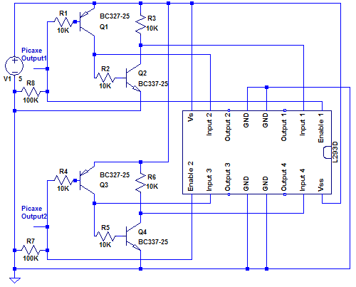
Here's the idea of the upper part of the circuit above (Picaxe output 1, Q1, Q2 and L293D's enable 1, input 1 and input 2):
When the Picaxe output 1 is low Q1 and Q2 are on. L293D's input 1 is pulled down by Q2 and input 2 pulled up by Q1 but that does not matter because Picaxe's output 1 is pulling enable 1 down.
When the Picaxe output 1 is high L293D's input 1 is pulled up by R3 because Q2 is off and input 2 is low because Q1 is off.
When the Picaxe output 1 is hi-z Q1 and Q2 are on. L293D's input 1 is pulled down by Q2 and input 2 pulled up by Q1. L293D's enable 1 is pulled up by Q1 base.
The lower part works just like the upper one.
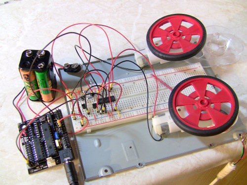
Here's a picture of the whole thing on breadboard and 28x1 is driving it:
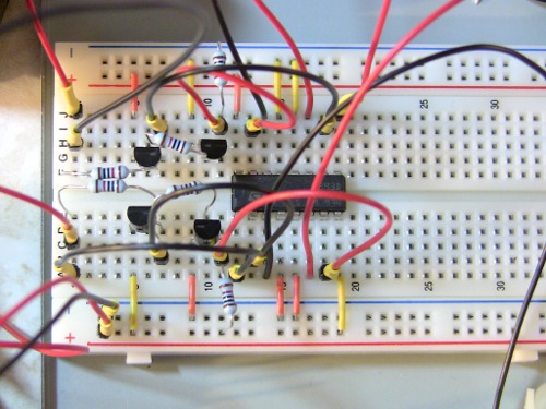
And a close up on breadboard:
There's also embedded video of the thing working at the top of the page if you happened to miss it. I hope this was helpful. Comments and corrections are welcome :-)
The code running motors on the video is this (also attached): main: ' Motor 1 off Motor 2 off low portc 0 low portc 1 pause 2000
' Motor 1 forward Motor 2 forward high portc 0 high portc 1 pause 2000
' Motor 1 backward Motor 2 backward dirsc = %00000000 pause 2000
' Motor 1 forward Motor 2 backward dirsc = %00000000 high portc 1 pause 2000
' Motor 1 backward Motor 2 forward dirsc = %00000000 high portc 0 pause 2000
Update Feb 24 2010: Schematic was missing pull down resistors. Now the schematic above should be ok. The reason why it was working on my tests with 28x1 was because I was using axe020 project board and it has pull down resistors on digital inputs (port c). It got me a bit worried when I first tried the circuit on 08 project board and it wasn't working. But it's running just fine now.
Update Feb 24 2010 (part 2): Added another video just for fun. This works with 08M too. I attached code for 08M too although it's almost identical to 28x1 code.
Very interesting When I get time, mabe I will try it with the Parallax Basic Stamp. I looks like it would work. I/O pins run scarce with H bridge stuff I am learning.
I think this works with pretty much any microcontroller as long as you can configure pins as inputs and outputs. Of course you need a bit more space for extra components and some changes to your code. Your code might get a few lines longer too if you want to store the states of other pins (not just configuring them all but just the one(s) you need).
It should work with those transistors or pretty much with any general purpose transistor (currents through transistors and switching frequencies are really low).
You might want to try building only one half of the schematic first (the “upper part” of the schematic). This way there’s less chance for errors. If you do it this way just use/connect these:
You mentioned a separate power supply. Have you tested it to make sure it works? Also, what voltages are you using with this circuit and how did you connect it to the circuit? L293D datasheet (at least the one I have, SGS-Thomson) says:
Vs and Vss max is 36V
Vss min is 4.5V (although it seems to work with lower voltages)
Vs min is Vss
Input and enable max is 7V
Input and enable min for high is 2.3V
When I used this circuit in my LadyBugBot clone I added pull-down resistors to L293D’s inputs 2 and 3. I think they are not really necessary (this circuit worked just fine for me) but I just wanted to make sure those inputs will not float. You can check the schematic for that in LadyBugBot clone page. Be warned: The schematic there is even more complicated because it has all component for the bot. You can also see the mess on the proto board
I’m sorry it’s taken me so long to reply, your comment is definitely helpful. unfortunately i used up all my resistors when i attempted to build the board so i have to run to radioshack hopefully sometime this week. i was using a 4 pack of double AAs just hooked up to the power lines in the breadboard. With my 28x1 board i just had the standard 3 AA pack. I think i may have been reading the schematic incorrectly. I’ll have to try again later this week, but thank you very much for your helpful reply
4 x AA (6V) for L293D and 3 x AA (4,5V) for 28x1 should be fine. I thought that different logic voltages may cause so trouble but according to L293D datasheet it’s ok: Input & enable high voltages are min 2,3V so it works at 4,5V (from 28x1).