


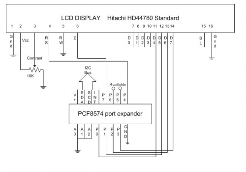
Any parallelly interfaced character LCD you get these days will have a Hitachi HD44780 chip or a different one compatible with the HD44780. These usually have 14 pins (16 if have backlight)
- D0-D7 is the bi-directional data bus
- R/W determines if we read from or write to the LCD
- RS stands for "register select". RS=0 means that the instruction register is selected. RS=1 means that the data register is selected. In other words, according to the status of RS pin, the data on the data bus is treated either as a command or character data.
- E pin enables or disables the LCD module. When Enable is low the LCD is disabled and the status of RS,R/W and the data bus will be ignored. When Enable pin is high the LCD is enabled and the status of the other control pins and data bus will be processed by the LCD. When writing to the display, data is transferred only on the high to low transition of this signal.
- Vo pin is for adjusting the contrast of the display. Usually, when this pin is grounded the pixels will be the darkest.
- Vcc is the power supply pin
Commands
The commands for HD44780 chip are:
- Function set (8-bit interface, 2 lines, 5*7 Pixels): 0x38
- Function set (8-bit interface, 1 line, 5*7 Pixels): 0x30
- Function set (4-bit interface, 2 lines, 5*7 Pixels): 0x28
- Function set (4-bit interface, 1 line, 5*7 Pixels): 0x20
- Scroll display one character right (all lines): 0x1E
- Scroll display one character left (all lines): 0x18
- Home (move cursor to top/left character position):0x02
- Move cursor one character left: 0x10
- Move cursor one character right: 0x14
- Turn on visible underline cursor: 0x0E
- Turn on visible blinking-block cursor: 0x0F
- Make cursor invisible: 0x0C
- Blank the display (without clearing): 0x08
- Restore the display (with cursor hidden): 0x0C
- Clear Screen: 0x01
- Set cursor position (DDRAM address): 0x80+ addr
- Set pointer in character-generator RAM (CG RAM address): 0x40+ addr
- Entry mode set: 0x04, 0x05, 0x06, 0x07
i.e. : %000001IS
where
I : 0 = Dec Cursor 1 = Inc Cursor
S : 0 = Cursor Move 1 = Display Shift
To send a command: set R/W pin to0 (write), set RS pin to 0 (command selected), put the command to data bus D0-D7.
Set E pin to 1 then to 0 (remember: data is transferred only on the high to low transition of this signal).
To send data: set R/W pin to0 (write), set RS pin to 1 (data selected), put the data to bus D0-D7, rise E and then back to 0.
Initialization
HD44780 based LCD displays MUST be initialized.
An internal reset circuit automatically initializes the HD44780U when the power is turned on.
The data sheet warns that under certain conditions, the lcd may fail to initialize properly when power is first applied. This is particulary likely if the Vdd supply does not rise to its correct operating voltage quickly enough. It is recommended that after power is applied a command sequence of 3 bytes of values $30 is sent to the module. This will guarantee that the module is in 8 bit mode and properly initialised.
The HDD44780 lcd control chip was designed to be compatible with 4-bit processor. Once the display is put in 4 bit mode, using the Function Set command, it is a simple matter of sending two nibbles instead of one byte, for each subsequent command or character. When using 4 bit mode only data lines D4 to D7 are used. Note that the Function set command for 4-bit interface, 2 lines, 5*7 Pixels is 0x28. So first use the Function set command $20 (4-bit interface, 1 line, 5*7 Pixels); from now on, all commands and data must be sent in two halves, the upper four bits first.
Now you can send the Function set command 0x28.
Take now the well-known PCF8574P. This is a general purpose eight-bit input/output chip.
The hard-coded address is: 0100.A2A1A0
The 0100 part is hard-coded in the PCF8574P.
The A2A1A0 is for us to choose. Make these bits one or zero by tying the corresponding pins to Vcc or Ground:
NOTE: Philips produces two variants of this IC: the PCF8574 and the PCF8574A. The only difference is the I2C chip address!
PCF8574 0100.A2A1A0
PCF8574A 0111.A2A1A0
Important: the I2C standard prescribes pull-up resistors on the SDA and SCL line. This is one of the most common mistakes when first using an I2C interface. Forget the pull-ups and your interface will not work (sigh!). Picaxe manual show resistors of 4k7 ohms.
Arduino don't need pull up resistor.
Now connect all together!
Sample Picaxe code
Please use a fixed size font or C&P this code to picaxe editor.
'
'
'
' schema:
'
' +---------------------------------------------------------------+
' | |
' | LCD DISPLAY Hitachi HD44780 Standard |
' | |
' | 1 2 3 4 5 6 7 8 9 10 11 12 13 14 15 16 |
' +-+---+---+---+---+---+---+---+---+---+---+---+---+---+---+---+-+
' | | | | | | | | | | | | | | | |
' GND V+ CNT RS RW E D0 D1 D2 D3 D4 D5 D6 D7 LV+ LGND
' | | | | | | | | | | | | | | | |
' = +5 | | = | | | | |
' | +-+ | | | | | | |
' | < | | | | | | |
' | 10K ><+ +------------------+ | | | |
' | < | | | | | |
' +-----+ | | | | | |
' | | | | | |
' | | | | | |
' | | | | | |
' | | | | | |
' to Picaxe I2C | | | | | |
' ^ ^ | | | | | |
' +5 | | ++ | | | | |
' | | | | | | | | | | | |
' +-+---+---+---+---+---+---+---+-+ | | | |
' | V+ SDA SCD INT P7 P6 P5 P4| | | | |
' | | | | | |
' D PCF8574 port expander | | | | |
' | | | | | |
' | A0 A1 A2 P0 P1 P2 P3 GND| | | | |
' +-+---+---+---+---+---+---+---+-+ | | | |
' | | | | | | | | | | | |
' +---+---+ | | | +------------------------+
' | | | +------------------------+
' gnd | +------------------------+
' +------------------------+
'
'
'
'
' name - 8574 bit - LCD
' ------ -------- ---------------
SYMBOL DB4 = 0 ; LCD Data Line 4 (pin 11)
SYMBOL DB5 = 1 ; LCD Data Line 5 (pin 12)
SYMBOL DB6 = 2 ; LCD Data Line 6 (pin 13)
SYMBOL DB7 = 3 ; LCD Data Line 7 (pin 14)
SYMBOL RS = 4 ; 0 = Command 1 = Data (pin 4)
; 5 free (to pin 15 for lcd bk light, for ex.)
; 6 free
SYMBOL E = 7 ; 0 = Idle 1 = Active (pin 6)
SYMBOL Addr8574 = $40 ; this is the 8574 I2C address
; A2=A1=A0=0 <-> x100 000x
SYMBOL RSCMDmask = %00000000 ; Select Command register
SYMBOL RSDATmask = %00010000 ; Select Data register = High P4 on 8574
SYMBOL Emask = %11100000 ; Enable = P7 on 8574
SYMBOL temp = b11
SYMBOL aByte = b12
SYMBOL rsbit = b13
SYMBOL index = b14
main:
GOSUB InitialiseLcd ; Initialise the LCD
mainloop:
aByte = $01 'clear
GOSUB SendCmdByte
aByte = 2 * 8 | $40 ; Program User Defined Character 2
GOSUB SendCmdByte
aByte = %00110 : GOSUB SendDataByte ; ##
aByte = %10110 : GOSUB SendDataByte ; # ##
aByte = %11111 : GOSUB SendDataByte ; #####
aByte = %00101 : GOSUB SendDataByte ; # #
aByte = %00100 : GOSUB SendDataByte ; #
aByte = %00100 : GOSUB SendDataByte ; #
aByte = %01010 : GOSUB SendDataByte ; # #
aByte = %10001 : GOSUB SendDataByte ; # #
aByte = 2 ; put User Defined Character 2
GOSUB SendCmdByte ' goto home
table 10, ("Let's make")
table 20, ("ROBOT")
for b0 = 10 to 19
readtable b0,aByte
GOSUB SendDataByte
next b0
aByte = $80 | $40 ; Put cursor at start of Line 2
GOSUB SendCmdByte
wait 1
for b0 = 20 to 24
readtable b0,aByte
GOSUB SendDataByte
next b0
wait 3
aByte = $80 | $0C ; Put cursor at start of Line 2
GOSUB SendCmdByte
aByte = 2 ; Display User Defined Character 2
GOSUB SendDataByte
wait 9
aByte = 1
GOSUB SendCmdByte
goto mainloop
' INITIALIZE LCD
' -----------------------------------------------------------------
'
InitialiseLcd:
' initialize I2C
i2cslave Addr8574, i2cslow, i2cbyte
for index = 0 TO 5
read index,aByte
gosub SendInitCmdByte
next
' Nibble commands - To initialise 4-bit mode
eeprom 0,( $33 ) ; %0011---- %0011---- 8-bit / 8-bit
eeprom 1,( $32 ) ; %0011---- %0010---- 8-bit / 4-bit
' Byte commands - To configure the LCD
;
; Display Format
; 4bit mode, 2 lines, 5x7
;
; 001LNF00
eeprom 2,( $28 ) ; %00101000
; L : 0 = 4-bit Mode 1 = 8-bit Mode
; N : 0 = 1 Line 1 = 2 Lines
; F : 0 = 5x7 Pixels 1 = N/A
;
; Setup Display
; Display ON, Cursor On, Cursor Steady
;
; 00001DCB
eeprom 3,( $0E ) ; %00001110
; D : 0 = Display Off 1 = Display On
; C : 0 = Cursor Off 1 = Cursor On
; B : 0 = Cursor Steady 1 = Cursor Flash
;
; Setup Cursor/Display
; Inc Cursor Cursor Move
;
; 000001IS
eeprom 4,( $06 ) ; %00000110 %000001IS Cursor Move
; I : 0 = Dec Cursor 1 = Inc Cursor
; S : 0 = Cursor Move 1 = Display Shift
eeprom 5,( $01 ) ; Clear Screen
return
' SEND INIT CMD BYTE - SEND CMD BYTE - SEND DATA BYTE
' -----------------------------------------------------------------
'
SendInitCmdByte:
pause 15 ; Delay 15mS at 4MHz
SendCmdByte:
rsbit = RSCMDmask ; Send to Command register
SendDataByte:
'
' put MSB OUT FIRTS
' via I2C
'
temp = aByte >> 4 | rsbit
gosub DirectSendCmd
'
' put LSB
'
temp = aByte & $0F | rsbit
rsbit = RSDATmask ; Send to Data register next
DirectSendCmd:
temp = temp xor Emask ' E=1
writei2c (temp) ' send to 8574 via I2C
temp = temp xor Emask ' E=0
writei2c (temp)
return
