I bought a couple of these JGA25 2430 motors that were advertised as encoder motors but they are not (I was wrong, they are encoders). But since I have them I want to hook them up to see if they will work for my project.
(Update) I pluggled the motor into my Arduino Uno and got it working. The code had a couple pins reversed. I guess these are encoders because supposedly you can derive the rpm using the pulseIn function. I can control the speed, and direction so far but still the pulseIn code escapes me - don’t understand how it works. Where do they get the signal cycle pulse number (45)? Is that related to the reduction number: 45:1 ?
I can see the advantage of using these motors, no motor controller needed and no motor controller library. Just plug them in and use th
em. Pretty cool.
I found the code below but dont quite understand how it works. Specifically everything following and including the for j loop. Can anyone interpret?
int i = 0;
unsigned long time = 0;
bool flag = HIGH;
void setup() {
// put your setup code here, to run once:
Serial.begin(115200);
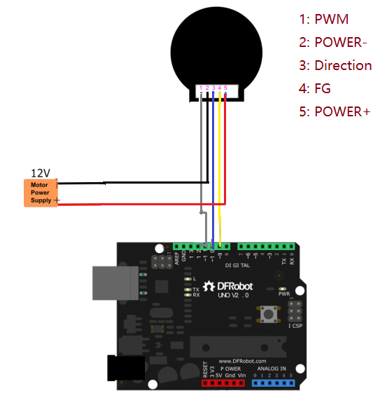
pinMode(10, OUTPUT); //PWM PIN 10 with PWM wire
pinMode(11, OUTPUT);//direction control PIN 11 with direction wire
}
void loop() {
// put your main code here, to run repeatedly:
if (millis() - time > 5000) {
flag = !flag;
digitalWrite(10, flag);
time = millis();
}
if (Serial.available()) {
analogWrite(11, Serial.parseInt()); //input speed (must be int)
delay(200);
}
for(int j = 0;j<8;j++) {
i += pulseIn(9, HIGH, 500000); //SIGNAL OUTPUT PIN 9 with white line,cycle = 2*i,1s = 1000000us,Signal cycle pulse number:27*2
}
i = i >> 3;
Serial.print(111111 / i); //speed r/min (60*1000000/(45*6*2*i))
Serial.println(" r/min");
i = 0;
}
From what I see in the datasheet, it is not mentioned to feature an encoder, it seems to be a brushless motor that includes a built-in motor driver.
For pulse number 45, here is what I found:
The FG pin seems to be a frequency output.
Signal cycle pulse number: 45*6 (Each cycle outputs 6 pulse)
This would act as an encoder to allows the user to receive feedback information concerning the speed of the motor.
This is all I could find with these information.
Let me know if this helps.
Thanks for your interest and input. Since I posted the question I found out a lot more too.
The JGA25 2430 (seemingly not available in US) motor is as you said, a brushless motor, similar to the the FIT0441 (available in US from DFROBOT) which has encoder attributes: you can control the speed of the motor, the direction, count rotations and calculate rpm and it is as you say, driverless - does not need a driver or even a driver library. You just plug it into the Arduino, set the direction and set the speed of the motor with the digitalWrite() analogWrite() functions. Simple and easy to use.
Here are my unknowns:
Where does the 45 in the 45*6 cycle pulses come from? Is that because it is a 45:1 ratio motor which I assume is 7200 rpm motor / 159 rpm geared rpm?
And if that is true then my version of this motor would be 7200 / 1550 or 4.6:1 ratio. So would my cycle pulses be 4.6 * 6 which is how many pulses there would be in one rotation of the axle?
Does FG mean “frequency generator”?
I still dont understand what he is doing in the code from the j loop and following. Why does he loop 8 times in the j loop, total the pulseIn count from FG, bit shift the total i to the right by 3, and then divide 111111 by i to get RPM? Blows my mind.
3.a. I just researched bit shifting - bit shifting to the right by 3 is the same as dividing by 8 which is the number of times he loops pulseIn.
3.b. Is he looping 8 times just to get an average and he chose 8 because it is a convenient number to use the bit shift >> 3 ? Could he have looped 9 times and divided by 9?
He has some mistakes in his code (setting wrong pins) but basically it does work.
Appreciate your interest. It is nice to be able to just plug a motor in without a motor driver and library to contend with and the motor is working great in my newest project.
I have a JGY-2430 hooked up to an Arduino.
It has a built in ESC (Elec. Speed Controller), as above, with the yellow wire giving pulses related to speed, I think. White wire is supposed to control speed. Anyone know how this should work?
I have tried 50 Hz pulses 1-2ms wide, which I thought would be 0-max speed, but no change in speed.
Thanks. This is a new project for me…
If you have it wired same as the example, you don’t have to create your own PWM signal.
Just use the above quoted command and send a speed value ( 0-255 I guess ) via serial console.
The feedback part is just for your peace_of_mind
Thanks for the reply. I have just tried using "analogWrite(5,MOD); " to the ‘speed’ input to the motor’s ESC (where MOD is a number 0-255). This is better than sending a ‘servo’ input of 1-2msec pulse, which did not control it.
I can see on a scope that I am getting a 1 kHZ PWM output, from 0-100% modulation, depending on the ‘MOD’ value. So, the software does what I wanted, in producing PWM.
However, the motor (driven from 12V) does not respond smoothly to this-
it stops at 100% modulation (5V input) and seems to be fastest at ~ 50% modulation.
… I guess I’ll just keep experimenting unless someone actually knows how the ‘speed’ input should work.