

Hi all,
I have some basic question about this DC motor. I found this motor have 5 Wire.
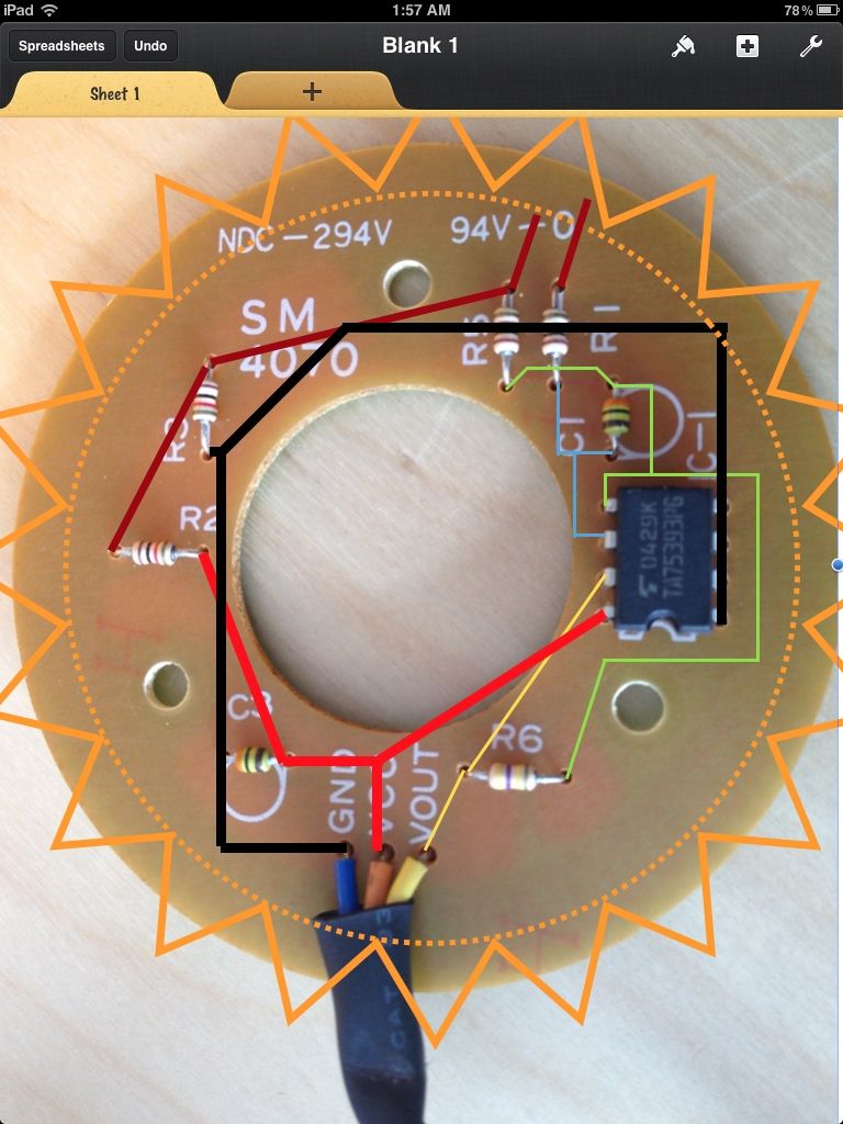
RED,BLACK,BLUE,YELLOW & ORANGE, image
The wire RED and BLACK wire are connected to motor coil directly and can be used just to simply run it.
BLUE, YELLOW & ORANGE are connected to an magnetic rotary Encoder.
There is an Megnatic Rotary disk attached to the other end of motor shaft and is fixed in such a way that it rotates along with the rotation of the Shaft. ImageA ImageB
The Circuit of the Three Wire image is hereA hereB
I would like to know how to use this DC6616 Motor and what applications/Purpose this can be used for.
Further Info: i used the normal Read analogvolt Sketch on Arduino whereby i connected the 5v to VCC and VOUT to A0 and GRD to GRD on Atmega2560.
I let the motor run with seperate powersupply using 12V on Red and Black wire and found the Analog readout was 2.5V after several interval of 0 eg 0,0,0,0,2.5,0,0,2.5,0,0,0,2.5
I tried to find after how many interval it repeates the 2.5V reading and failed to do so as the repeatation is sometime after 4 0's sometime after 2 0's sometime 3 0's
Also i disconnected the powersupply to motor and rotate the shaft manually by hand and found on slow rotation it reads nothing only 0's
when i give it a sudden rotation then it spikes to 2.5V and then back to 0.
i hope the above info would be helpful for guys out there who exactly know what this motor encoder is.