

Data Bus, is the 3rd place winner of the 2012 Sparkfun Autonomous Vehicle Competition (AVC) and veteran of the 2011 Sparkfun AVC. It is a mini, autonomous rover robot based on a 1:10 scale RC truck.
With only three sensors, a simple Kalman Filter, and a total cost of around $650, the robot was able to achieve a top speed of around 20mph, with a total raw time around the building of 37 seconds and a cross track error of ~1 meter (based purely on eyeballing it while chasing it several times around the SFE building in my WRX).
Here's the nickle tour of the robot, it's features, sensors, software, and more.
Chassis
http://www.bot-thoughts.com/2011/02/robotifying-rc-truck.html
The robot started as an ElectrixRC "Circuit" 1:10 stadium truck. At $130, it was the least expensive 1:10 RC truck I could find at my local RC Hobbies. It's not cheap, just a good value. It's tough, easily customized, good parts support, and has a loyal fanbase.
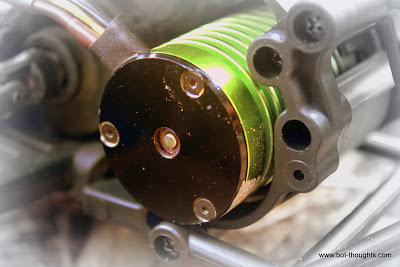
It runs a Tacon 3000Kv brushless motor, Hobbywing 35A ESC, 2.4GHz FlySky 3 channel receiver, and 2S, 4000mAH 25C Gens Ace LiPo battery, ElectrixRC 'hard' springs, and Traxxas Anaconda tires on 2.8" All Star black chrome wheels.
Suspension tuning completed the chassis work. I used 50wt oil in all four shocks, and adjusted ride height in back with springs inserted below the shock pistons. The result was a lower center of gravity and much flatter turns.
Body
The body is a Parma PSE "Skool Bus" lexan body custom painted by yours truly with custom decals printed on inkjet self-adhesive paper and coated with automotive clear coat.
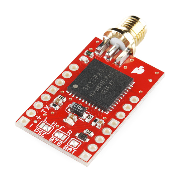 |
| Venus GPS |
Sensors
Data Bus uses only three sensors. A Gyro, a GPS, and wheel encoders.
GPS
The GPS is a 20Hz Venus638FLPX on Sparkfun breakout board mounted inside with a roof-mounted patch antenna and a ground plane cut from a square of tin that's good for 5-10db signal gain. GPS supplies heading information. The robot ignores GPS position information.
Gyro
http://www.bot-thoughts.com/2012/04/avc-precision-gyro-calibration-reloaded.html
Additional heading information comes from an STM L3G4200D gyro on a Pololu minIMU-9, mounted on an aluminum bracket up front. Communication is via I2C at 400kHz. The gyro is sampled at 100Hz.
Encoders
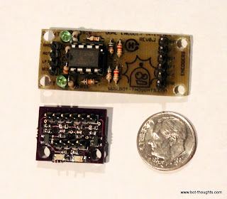 |
| Redesigned encoder board |
http://www.bot-thoughts.com/2011/03/avc-bot-wheel-encoders.html
Wheel encoders on both rear wheels provides accurate distance measurement. The 32-stripe wheel encoder discs were created with my WheelEncoderGenerator cross-platform java application.
Sparkfun QRE1113 sensor boards mounted to the bearing carriers sense the stripes and send signals to a tiny surface mount interface board I redesigned using comparators in a Schmitt-trigger configuration.
Experimentation, Simulation, Analysis
http://www.bot-thoughts.com/2011/10/why-wrights-flew-first.html
http://www.bot-thoughts.com/2011/12/magnetometers-and-motors.html
http://www.bot-thoughts.com/2012/03/magnetometer-calibration-machine.html
http://www.bot-thoughts.com/2012/02/avc-is-compass-necessary.html
http://www.bot-thoughts.com/2012/03/avc-is-3d-compass-necessary.html
http://www.bot-thoughts.com/2012/03/magnetometer-calibration-error.html
http://www.bot-thoughts.com/2012/02/avc-encoders-quantization-error.html
I spent quite a bit of time testing, experimenting, understanding and modeling the error modes of the various sensors and their impact on position estimation error. All that up front work explains the unorthodox sensor choices, particularly ditching the compass and using only heading data from the GPS. Fortunately, all the work and the odd choices seemed to have been successful.
Naturally, the sensors are not of much use without a way to use them to estimate position and heading, aka pose.

Pose Estimation
Heading is incredibly important in the Sparkfun AVC. An error of only a couple of degrees is the difference between crashing and finishing. The solution on Data Bus feeds lag-compensated gyro and GPS heading data into a Kalman Filter, using the results to update current heading and position with that historical estimate.
Gyro data is the foundation of the heading estimate. It's corrected for bias using heading data from the GPS. Unfortunately the GPS does its own massive amount of filtering and the result is a reduced dynamic range and lag.
http://www.bot-thoughts.com/2012/05/avc-whats-wrong-with-data-bus.html
By saving a second's worth of gyro data and feeding that into a Kalman Filter, a very good estimate is generated. From this, the gyro-based heading is updated. The end result is a heading estimate with high dynamic range and negligible bias.
Meanwhile distance traveled is given by the average distance of the wheel encoders. I calibrated the wheel encoders to Google Earth, my waypoint editor, and found the error falls below 1%. So the robot knows how far it's gone and in what direction, giving a position estimate. The position is estimated in cartesian coordinates which I did for one very good reason: updating the position based on the historical heading estimate.
If we know what direction we were pointing a second ago, we can not only update gyro heading calculations up to present, but, using a rotation matrix, we can update the last second's worth of position estimates up to present very quickly.
Microcontroller
http://www.bot-thoughts.com/2011/05/choosing-mcu-atmega-xmega-or-arm.html
http://www.bot-thoughts.com/2012/05/avc-brain-transplant-and-updates.html
 |
| mbed on motherboard |
The microcontroller is an NXP mbed, a NXP LPC1768 Cortex M3 running at 96MHz with 512KB flash, 64KB SRAM, and a plethora of I2C, ADC, UART, SPI and other peripherals. The mbed is mounted on a custom PCB fabricated at Bot Thoughts labs (a messy corner of our garage).
The ample computing power, flash memory, and available RAM open up possibilities that are simply unattainable on the typical 8-bit, low speed microcontroller.
The mbed incorporates a mass storage USB flash drive which stores the configuration file for the robot. The file contains waypoints, compass declination, magnetometer calibration, speed, turning parameters, GPS baud rate, and more. The configuration file saves time by avoiding recompiles.
User Interfaces
http://www.bot-thoughts.com/2012/04/avc-data-bus-interfaces-and.html
 |
| Sparkfun Serial Graphic LCD user interface |
The robot features two primary time-saving interfaces. The first is a serial, menu-based interface accessible through the built-in USB to serial adapter on the mbed.
The menu gives access to instrument diagnostics, software reset, a unix-like shell for managing and downloading log files, a bridge to raw GPS output to permit PC client software to directly configure the GPS, output for AHRS visualization, Mavlink data output for use with a Ground Control Station, and more.
Secondly, the robot features an onboard interface consisting of a Sparkfun 128x64 graphical LCD display and 3 buttons on the Bus body. Status information is displayed and various calibration functions are available. Most importantly, this is the interface used to tell the robot to start racing.
Data Logging
http://www.bot-thoughts.com/2010/02/logging-data-to-sd-cards.html
Data is logged as text CSV to an onboard FAT-32, 2G microSD card connected to one of the mbed SPI ports. Around 20 system state values are logged at a rate of 50Hz and typically take no more than 150usec to write but the logging is buffered and done in the non-time critical outer loop. Logfiles are named with sequential numbers.
Offline analysis scripts in Processing, perl, and Octave plot and visualize the sensor data, or prepare KLM files for display in Google Earth. The onboard shell command 'send' in combination with a customized Java serial terminal program initiates on-the-fly download of logfiles.
Power Supply
 |
| Lots and lots of wires... |
The main electronics power supply is a Pololu 5V, 3.5A step-down (buck) switching regulator fed by the same battery powering the ESC and RC receiver. The mbed's onboard 3.3V regulator supplies power to all the 3.3V circuits.
Wiring
All the wiring uses 0.1" pin headers and crimped and soldered female connectors on custom cables, all consistently color coded to eliminate race day goofs. I've learned that loose connections and rats nests of wiring suck, so I made a concerted effort to keep things somewhat organized underhood.
Printed Circuit Boards
Eagle board and circuit files, etc.
Because it's fun and because I hate breadboards for anything but prototyping, all the custom circuits are implemented on custom board designs. Two boards were professionally fabricated through the DorkbotPDX PCB service; the rest were etched at home.
For an added touch of elegance, I emblazoned each of the homebrew PCBs with a Bot Thoughts logo using the toner transfer method for "silk screening" After transfering the toner, each board is sprayed with clear acrylic for a pseudo-professional look. Each board carries an OSHW logo as well as the entire robot is open source.
Safety
http://www.bot-thoughts.com/2011/03/avc-bot-kill-switch.html

An RC switch (multiplexer) circuit based on designs online enables me to take control of the robot within a few milliseconds at any time by switching on the remote control transmitter. Control was returned to the microcontroller by switching off the transmitter.
The circuit takes pulses from the receiver and pumps up a capacitor, reaching a voltage that then controls a 74HC244 bus driver acting as a multiplexer.
The circuit is populated onto a custom PCB created at Bot Thoughts labs.
Software
mbed code
Data Bus Code Repository
Ranger Board Software
Analysis Software
Ground Control Software (such as it is...)
The software onboard DataBus is written in a mix of C and C++ in the mbed cloud IDE and tallies up to almost 20,000 lines at last count. The mbed libraries abstract interfaces to the microcontroller peripherals (Serial, I2C, ADC, etc.) I reused as much code from others as I could.
For example, I did a custom port of TinyGPS to mbed parses NMEA data from the GPS and provide methods for polling the availability of new GPS data. GGA and RMC sentences are parsed, only. I reused others' sensor libraries where I could. Most of the code base for Data Bus was developed last year by me.
Analysis
http://www.bot-thoughts.com/2012/04/avc-first-autonomous-runs.html
http://www.bot-thoughts.com/2012/05/avc-visualizing-position.html
This year, most of the effort went towards improved sensors and revised position and heading estimation software. To that end, quite a bit of additional software is written in Perl and Octave to process and analyze logs from the Bus. A Processing program does simple visual playback of data runs, and this program was adapted as a rudimentary simulation program.

Competes in the Sparkfun AVC, drives around building as fast as possible
- Control method: autonomous
- CPU: mbed ARM Cortex M3, 96MHz
- Power source: 25C 2S 4000mAH LIPO
- Programming language: C++, C
- Sensors / input devices: encoders, GPS, gyro
- Target environment: outdoor
This is a companion discussion topic for the original entry at https://community.robotshop.com/robots/show/data-bus-autonomous-ground-vehicle