Hi,
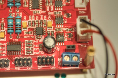
I have fried my 4 channel motor driver and don't know how this can happpen. As you can see in the picture the Dual FET IC U10 for motor 4 is blown away. This happened during a first test of my IOIO-SHR v2 robot. Before connecting the motor driver the program has been tested with an oscilloscope, all Outputs are working as expected. All connections has been double checked. Power supply testet with an voltmeter. Each PWM pin can be controlled from the Android phone with a Slider of my test app. PWM frequency was 1kHz.

Everything works fine I can control the speed of each motor. Both direction pins were LOW during the test, so the motors run only in one direction. After 2minutes playing around I put one slider to 100% PWM. A few seconds later blue smoke comes out of the board. What have I done wrong?
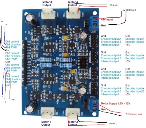
Here is a picture of the schematic I have used. Motor driver 2 and 4 has been used. 5V logic power from the IOIO board. 7.2V motor power from a battery pack. PWM , DIR for each motor has been connected to the IOIO pin 3,4,13,14. The IOIO board is running with 3.3V and so the outputs has only 3.3V, too. Could this be a cause?

Thank you OddBot.Yesterday I
Thank you OddBot.
Yesterday I repeated the test with motor driver 1 and 3. So far no problems, but I avoid to do 100% PWM, making a speed limit to 90% in the software. Maybe it was problem with the logic power wires and vibrations coming from the motors. The connection wasn’t really tight. I will use the screw terminals now, not the sockets.
For the direction pin, I will use a pullup resistor and the open drain feature for the direction outputs of the IOIO. This will give me 5V on the output. Just for security reasons, because I saw in the schematic, that the direction pin is going directly to one of the power FETs.
I will definitly use the current sense pins from the board. This is a great feature of this board.
We will see, if the encoder pins will supported in a future release of the IOIO firmware. If not a ATtiny with I2C interface will do this job.
Is it save to switch the FET directly without a line resistor? Will this work with 3.3V? Don’t know nothing about the maximum output current of the IOIO pins. Maybe I will use a separate driver stage between IOIO and the motor controller for the direction pins.
It happened again! One week
It happened again! One week before Campus Party 2 motor FETs blew up. A few days before I added a transistor as level shifter from 3.3V to 5V for each direction pin. That worked for some time. But without any warning during a drive test one of the motors just stops and blue smoke came out of the motor controller.
I gave up with this motor controller and switched it against a RN-VNH2 dual motor controller with 2 VNH3SP30 motor drivers. No more problems so far. IOIO-Rover works since 2 weeks and during the campus party now with this motor driver.


