


etchasketch.dwg_.zip (69073Bytes)
Code_Name__EAS_v2.pde.zip (2415Bytes)
da Vinci is an etch-a-sketch robot. He is capable of etching low resolution images in grey-scale. Let’s get to the build process.
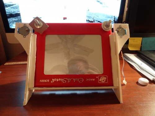
I first went searching for an etch-a-sketch. You would think I would have one already, but nope. I think every one should have a Rubik's Cube, an etch-a-sketch, and a slinky. I looked online at Walmart and supposively they are not sold in stores. No one buys these things anymore? I don't know why. Playing with the x and y movement is awesome!
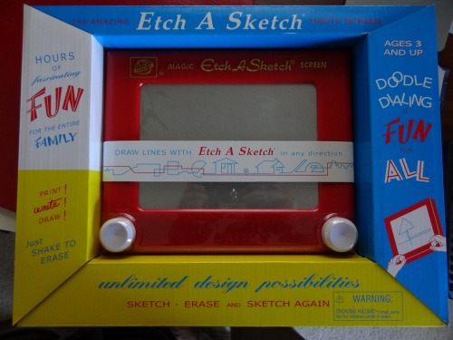
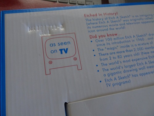
Come on kids, "as seen on TV"
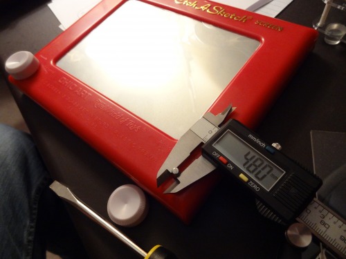
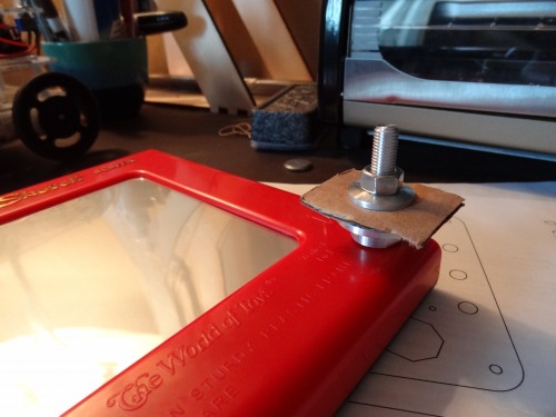
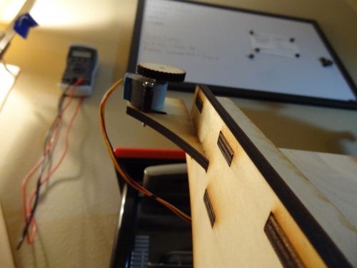
Well the knobs easily popped off. I measured the diameter of the shaft. I will need this later. Some how I have to spin that.
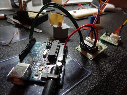
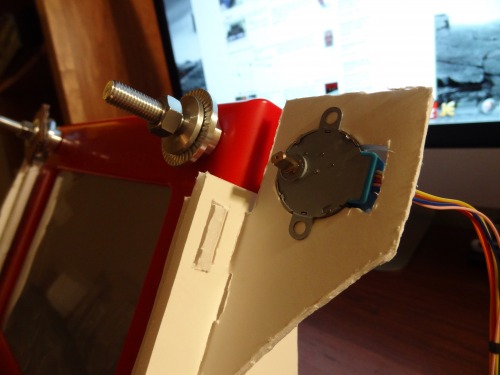
Well I think it is obvious that I went with stepper motors. I decided I would use stepper motors and gears to spin the etch-a-sketch's shafts. I got these 5v stepper motors and controllers at yourduino.com. I saw the ad for them on the front page of LMR. Actually that ad inspired me to make this whole project. So much for disliking ads...
One of the controllers did have a bad soldering joint I had to fix.
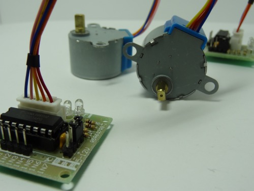
I hooked them up to an Arduino and gave them a test using the Arduino stepper motor library. They worked (slowly). I was pleased. That's all I have to say about that.
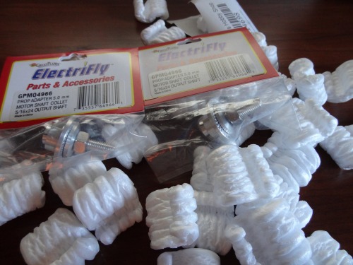
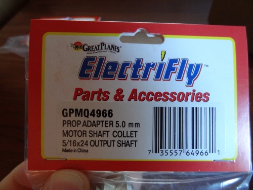
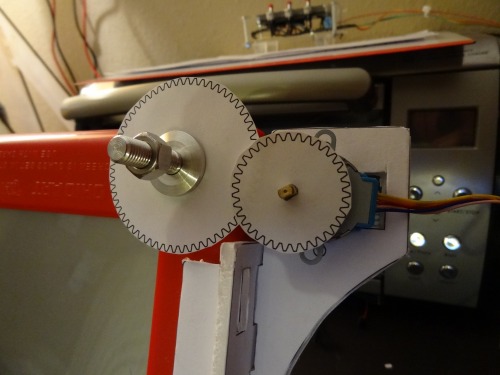
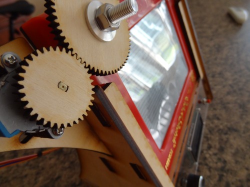
So next I had to tackle the issue of getting gears on the shafts of the etch-a-sketch. Whatever I did, I did not want it to be permanently on. So that elminates gluing. I could try and press fit a gear to the shaft, but I do not know how likely that is to work. I remembered I used a "collet" on one of my RC airplanes that did exactly what I needed. Would you know I found a 5mm collet online (they were not as cheap as I was expecting). The shafts of the etch-a-sketch are 4.8mm. Sounds like it was meant to be.
I have ordered many packages, but few have came in packing peanuts.
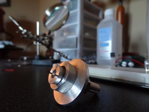
I put some washers and a little cardboard in the collet and tightened it onto the shaft. Eventually a gear goes where I put the filler (the washers and cardboard). It has a very good grip.
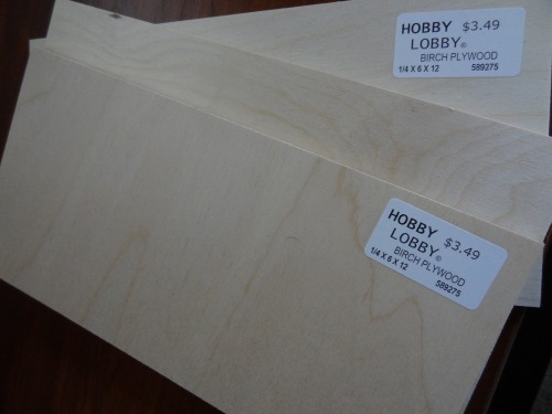
So next I needed to design the parts that would become "da Vinci." First I had to decide what they would be made of. Acrylic? Wood? Gold? Ok the last one is joke. I went with wood because it is strong and easy to glue. The local hardware store does not have nice plywood. So I ordered some hobby grade stuff online. This is the good stuff. So good in fact that I only had the money for 3 6"x12" sheets. That set my first design contraint.
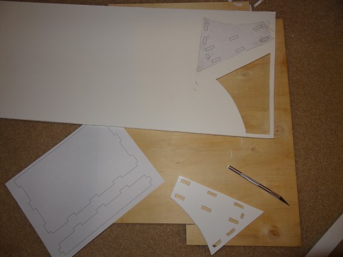
It was time to start CADing. For the first time, I cut out the design in foam board to see how it would fit together. This was crucial because with only 3 sheets of plywood, I had little room to mess up.
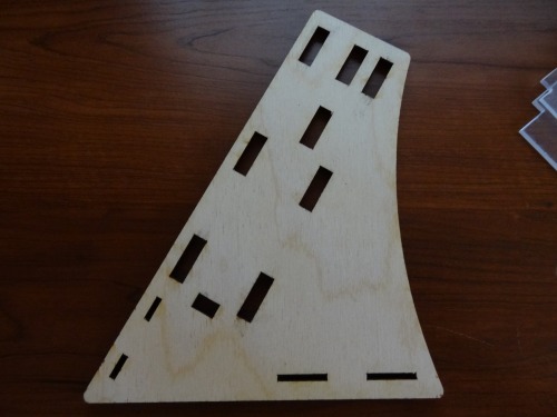
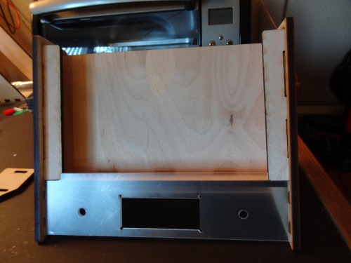
This was my initial design. The whole thing is angled back a little like a picture frame.
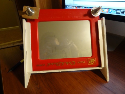
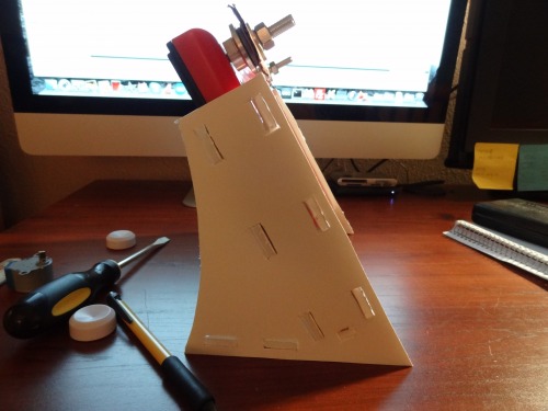
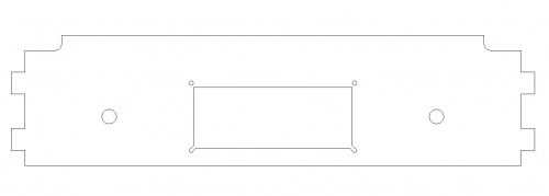
There were a few things that were obviously missing in this design that I knew I would eventually add. The first is a front panel that would house a LCD, potentiometer, and a button. The second was a way of mounting the motors.
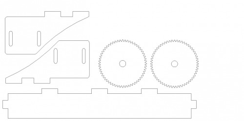
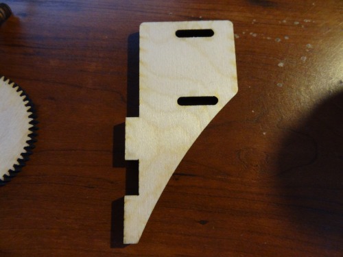
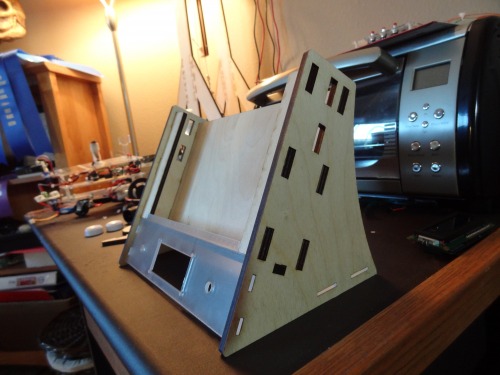
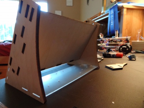
I went ahead and edited the design to include motors mounts. This is what I came up with:
As you may have guessed, there were issues with this first design. So onto design #2. I added the front panel and tweaked what needed to be tweaked.
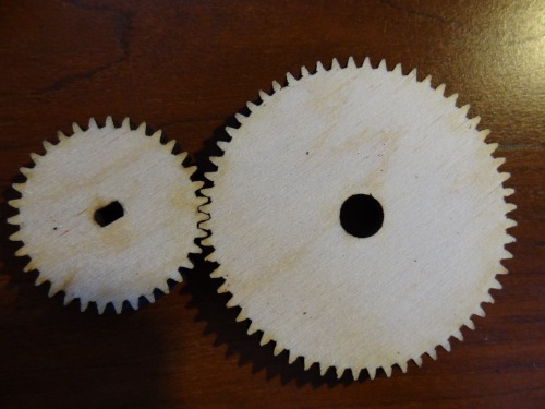
The last things to design were the gears. In fact, I did not design them at all. I found a website with CAD files of different gears. I found ones that would worked, scaled them, and ended up with this:
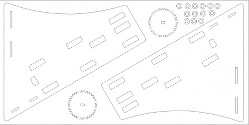
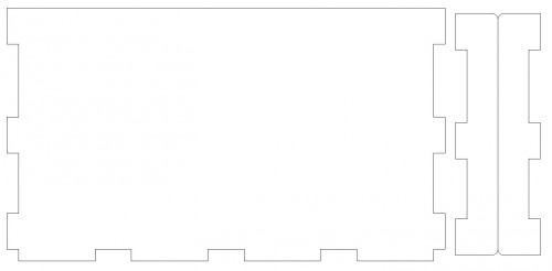
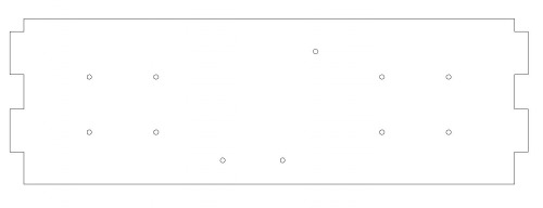
I present to you the final design:
The wooden pieces:
The acrylic pieces:
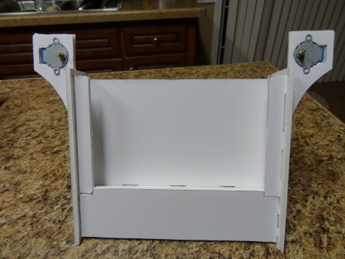
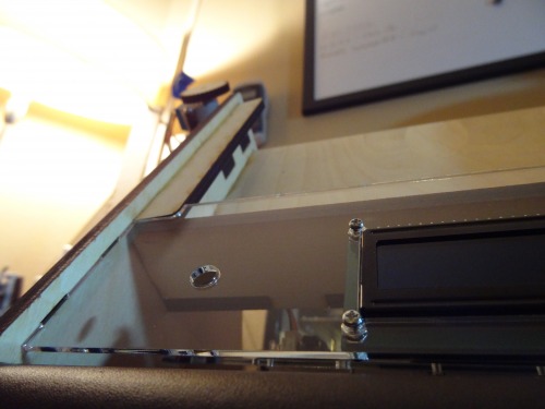
With the design finalized, I went to school to cut it out on a laser cutter. It took 2 passes of the laser cutter to cut all the way through the wood. The gears came out better than I thought they would. Below are the parts freshly cut out and temporarily assembled.
Next I glued all the wood pieces together. The acrylic pieces are not glued in. They are simply sandwiched into the design. Now all the hardware is complete.
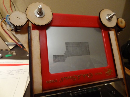
With the electronics partially complete, I did a quick scribble test. This program simply was etching away a section of the screen to reveal the inner workings of the etch-a-sketch.
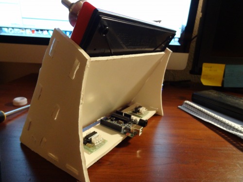
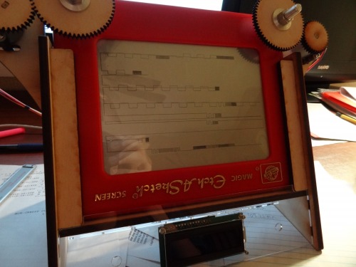
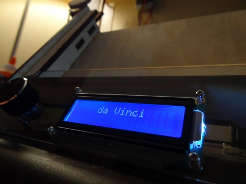
Well the scribble test was a success, but I wanted to try something more. At this time I was still waiting on the rest of the electronics (SD card shield, SD card, potentiometer, and a button). I decided I could still generate an image and save it in an array in the micro-controller’s program memory. So I started working on da Vinci’s code (not the book :P). Here is a photo I took while I was writing and tweaking the program:
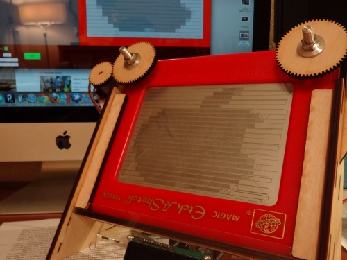
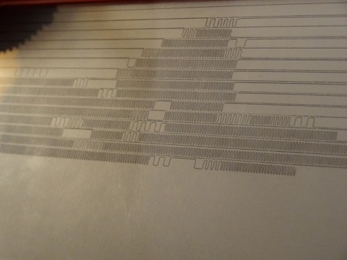
Once I finished testing and tweaking the code, I finally was able to etch a low resolution Apple logo. Success!
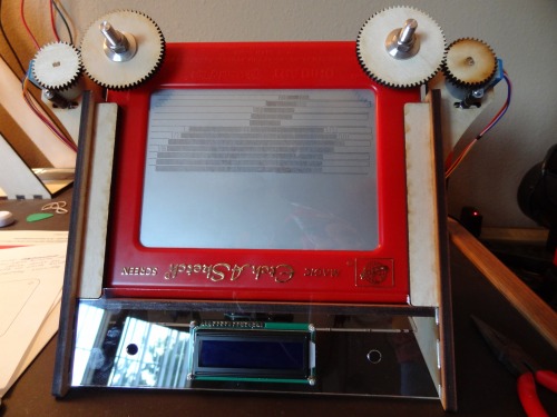
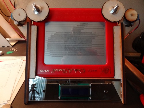
It took some courage, but I erased the etch-a-sketch and tried to etch another image. This time I did the Adafruit logo, which is a flower.
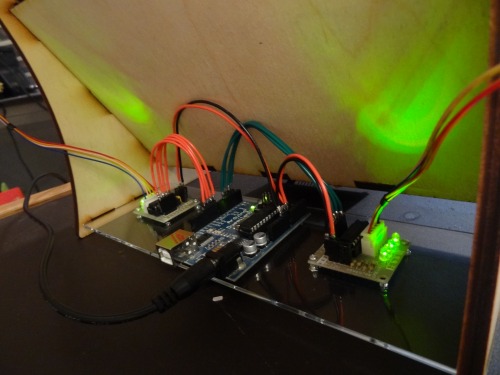
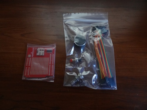
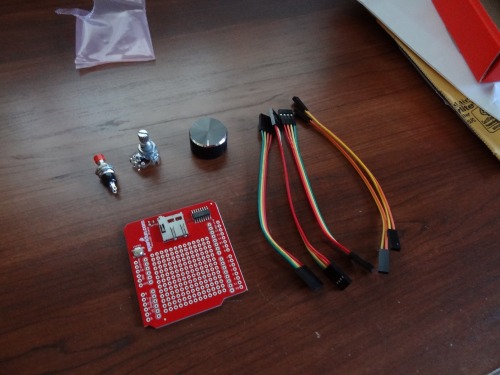
The mail finally arrived with the rest of my electronics. I received an Arduino microSD card Shield, potentiometer, knob, push button, and some cables.
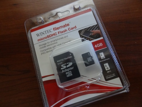
I also ordered a 4GB microSD card ($6 at Walmart). This card will store a bunch of data files for etching images.
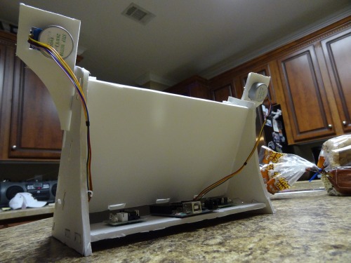
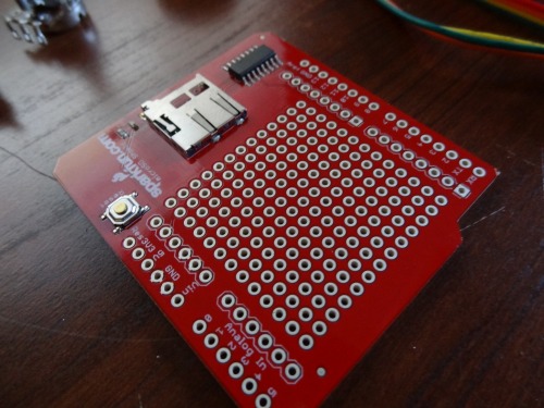
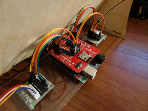
The prototyping area on the microSD card shield was the selling point to me. It allowed me to easily wire up all of the required connections. This included 8 digital outputs for the stepper motor controllers, serial communication connection to the ezLCDuino, 1 digital input for the button, 1 analog input for the potentiometer, and of course necessary power distribution.
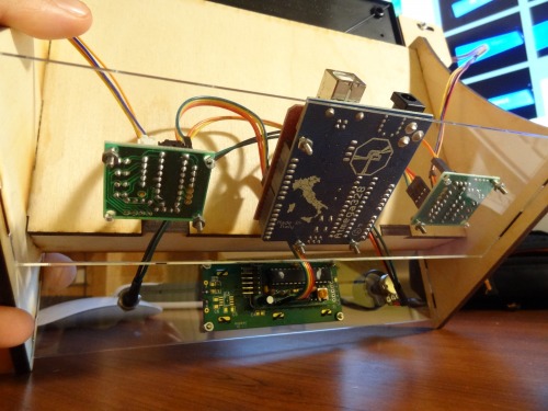
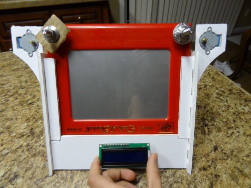
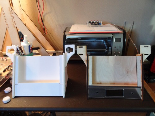
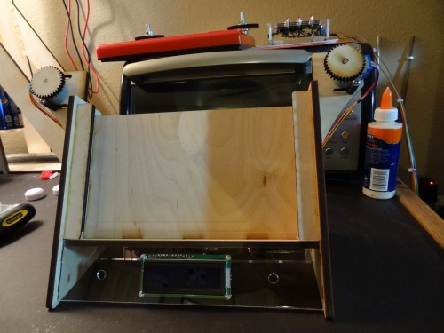
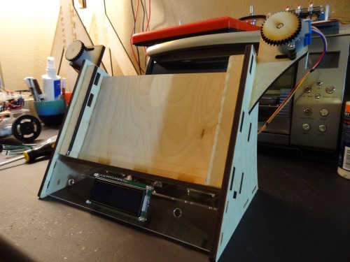
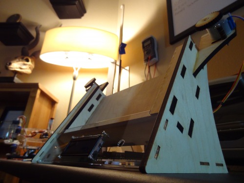
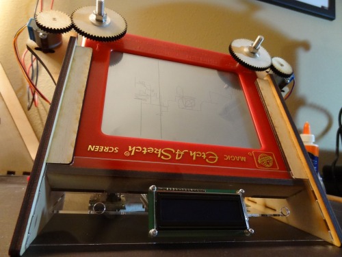
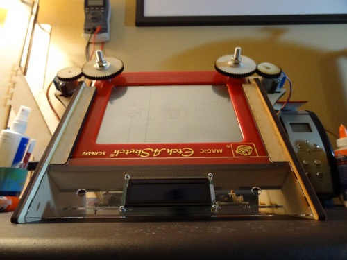
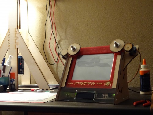
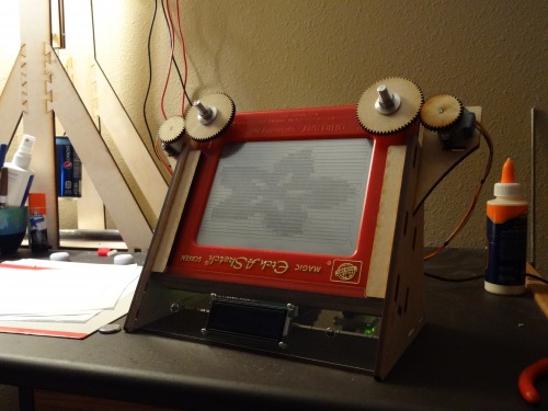
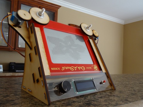
That concludes the build process. They grow up so fast! Here are some final pictures:
Time to Talk Software
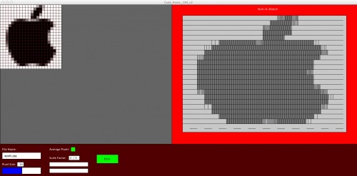
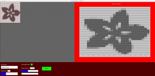
First let me talk about the computer software I wrote. Below are some images you should have already seen:
Above are two different screen shots of the piece of software I wrote using the Processing language (I love this language and use it for just about everything). This program takes an image, averages the pixels, displays a preview, and then generates a file. Ok that was a lot of stuff. Let me break it down:
Step 1 (“takes an image”): As you can see in the screen shot, there are quite a few different controls in the bottom left of the program. The upper most box is labeled “file name.” This is where the user simply types in the name of the image file they would like to load into the software. The image files must be in the Processing Sketch’s (sketch is just what they call a Processing program) folder to be loaded in, else there will be an error. The image will automatically be scaled to fit within the window, but there are user controls for scaling as well. The “scale factor” control allows the user to alter the scale of the image. There are numerator and denominator slide control bars. This is how the user sets the scale factor, which is in the form of a fraction. The program will not react to a set scale that is too big to display the image properly within the window.
Step 2 (“averages the pixels”): In order to etch the image on the etch-a-sketch it needs a resolution adjustment. Obviously an image with tons of pixels is simply impossible to display on an etch-a-sketch. This is not an HD T.V. we are talking about. So what the program does to lower the resolution is what I call “averaging the pixels.” There are two more controls I will bring your attention to, the “pixel size” and “average pixels” controls. These control the image averaging. The pixel size slide control bar is what sets the size of the averaging grid. You can see this red grid in the screen shots above. It is overlaid on the loaded image. The length of each side of the squares in the grid is equal to the pixels size set by the user. The smaller the pixel size, the tighter the grid, and the higher resolution the image is when averaged. The larger the pixel size... well you get the idea. Simply setting the grid size does not average the image. The “average pixels” check box must be checked for the image to be averaged. When this is checked, the program takes all of the pixels in each square of the grid and averages their grey-scale value (i.e. all images are converted to shades of grey). It then display a square over the picture that represents this average grey-scale value, and you are presented with a lower resolution image.
Step 3 (“displays a preview”): The last control is the “Etch” button. When this is enabled, the program will virtually etch the image. There is a “virtual” etch-a-sketch on the right side of the software window. This virtual etch-a-sketch’s screen is almost exactly the same size of real one. The program takes the data from the averaged image and displays it as lines on the virtual etch-a-sketch. Different grey-scale values are created by varying the distance between each line. This generated preview and the actual etched image on da Vinci look very similar, so that is good. You wouldn’t want to etch an image, which takes hours, and not know what it is going to look like in the end would you? So the feature is very handy, but I actually put that feature in way before I built da Vinci simply to see how well the software worked. It is very common for me to write software for a project I have yet to start.
Step 4 (“generates a file”): Finally the last step is to generate a file. This is the whole reason the program was created, to extract useful data from an image that I could then read into da Vinci and etch. This file is saved in the Processing Sketch’s folder. The name of the file is the same name as the loaded image and the extension is .txt. The contents of the file includes the width of each column in pixels, the number of rows, the number of columns, and the etch width for each averaged grey-scale value. The etch width is the number of pixels between each line in preview image. This file can then be put onto a microSD card, which is then inserted into da Vinci.
Now that we have data on a microSD card da Vinci’s Arduino program is ready to take over.
The Arduino program is pretty simple, but I will break it down into steps again.
Step 1: The user selects which file to etch. The user can navigate through the different file names using the potentiometer. The potentiometer’s analog value gets mapped to the number of files on the SD card. The file that corresponds with that number is displayed on the ezLCDuino (the ezLCDuino is a LCD with an Arduino backpack I made). The communication between the main Arduino micro-controller and the ezLCDuino is done over serial using Bill Porter’s EasyTransfer Library. When the user has selected the file they want etched they can hit the button to begin etching.
Step 2: This is the second and last step. The data of the chosen file on the microSD card is read in. The width of each column, the number of rows, and the number of columns first get put into variables. The width of each column is used to fit the image within the etch-a-sketch’s screen. The number of rows and columns are simply used to terminate for loops. One by one, the etch width data for each index of the image is read in and etched. This etch width is originally in pixels, but is then scaled to stepper motor steps. After each row is etched the program returns the etch-a-sketch’s stylus to the left hand side before etching the next row.
General Comments: There were a lot of little things to figure out and add in the code. Most of it was compensation for backlash and slop. It would be hard to completely explain all of the nuances in the code. So I have simplified the concept a little in my explanation.
https://www.youtube.com/watch?v=q2LIMYKQLXE
