Custom Motor Driver Debugging

31dq03.pdf (39216Bytes)
DC_Motor_driver_2A.pdf (17613Bytes)
1773.pdf (611634Bytes)
BC108A.pdf (273617Bytes)
fixed.JPG (264619Bytes)

Hello LMR!

I built a motor driver, look:

Cool isnt it? Of course it doesn't work as intended, but hopefully you guys can help me fix that. Lets take a look at the details first, and afterwards my problem.

The motor driver is built on a LN298N H-Bridge using a tri-state switch to control the directions and PWM input to control speed of the motors. Yes, it's supposed to drive two motors using up to 2A. In addition I've added a low-dropout volt regulator for +5v logic. I've used eight 31DQ04 40V 3.3A Schottky's as kickback diodes, just because I didn't have anything else suitable. The schematics for the driver is the same as found in this tutorial(i've added it for download at the bottom of this post as well).

In my test setup I used 2x 11.1v Lipo's connected in serial giving around 24v output. A 6V Ni-Mh pack was used on the logic side. Motors hooked up are two Pitman 19.1V GM8712 gearmotors, with a 60.5:1 reducing gearbox and a arduino was used to control the I/0 connections.

In my code I set all pins as OUTPUT and used the following in the main loop:

digitalWrite(m0_io_pin, LOW);
digitalWrite(m1_io_pin, LOW);
analogWrite(m0_pwm_pin, 255);
analogWrite(m1_pwm_pin, 255);
delay(3000);
digitalWrite(m0_io_pin, HIGH);
digitalWrite(m1_io_pin, HIGH);
analogWrite(m0_pwm_pin, 255);
analogWrite(m1_pwm_pin, 255);
delay(5000);

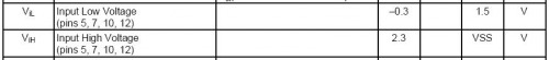
The logic is that if I set m_io_pin to low the motor should spin one way, setting it to high should make it spin the other way. The logic is easily explaind here. Testing the has shown that when mN_io_pin is LOW the collector of my transistor will output ~2v, while when the mN_io_pin's are brought HIGH the collector outputs ~4V.

My problem is that the motors only spin when the mN_io_pins are brought LOW.

Hopefully someone has a simple solution to my mess :)

UPDATE: Oh, well. Wasnt able to let my burned chip sit still for too long. I must have done something horrible wrong yesterday as I had 30cm spark and a small campfire for a couple of seconds. I created a new breadboard circut using a SN754410NE instead of the LN298N. I think If I put 2x of these H-bridges in parallel they'll provide me with enough current to drive the motors i got. This is a new picture of the setup on a breadboard:

Looks very cool.
Looking at the schematic it seems that the collector resistors R5, R8 should be have a lower value. Maybe this is the cause for the misbehaviour. The transistors can not draw enough current in the HIGH state. Instead 10k I would suggest 1k or 2k.

I’ve identified a likely

I’ve identified a likely candidate for the cause of the problem; check out this excerpt from the LN298N datasheet:

LN298N_Excerpt.jpg

Vss in your case is naturally +5V.
You said that the voltage at your transistor's collector alternated between ~2V and ~4V, so comparing those levels to the datasheet info we can see that ~4V is happily within the Vih zone, whereas ~2V falls into the 'forbidden zone', and doesn't comply with the required voltage to match Vil.
Since I don't know what transistors you're using I'll assume that the transistor's Vce saturation voltage is below 1.5V (if it isn't you'll need to use different transistors). If Vce sat is less than 1.5V, then you'll simply need to provide the base with more current so it can turn on harder and pull that collector voltage closer to ground. All you have to do is change the base resistor to something of a lower value (I can help you choose a value if you give me the transistor's name).

I haven't looked too far into the rest of the circuit, since I'm pretty sure that's the problem, but everything else seems to be all good.

Nice little design BTW, and the PCB looks very clean =D

Shouldn’t R5 and R8 be

Shouldn’t R5 and R8 be higher if anything? The collector voltage (Vc) will be Vss (+5V) minus the resistor voltage drop (Vr), so:
• Vr = IrR5, where Ir is the transistor collector current which is βIb.
• The base current (Ib) is fixed due to the static base resistor and base-emitter voltage drop, and β is also a fixed transistor parameter, so Ir is a constant.
• Vc = Vss - Vr = 5V - Ir*R5
Therefore making R5 (or R8) larger will lower the collector voltage.

Sounds logic to me and

Sounds logic to me and thanks for the answers both of you.

Just got a second to reply now before I prepare dinner, so i’ll just write down the transistor I use. They are regular NPN types called BC108A. Almost the same as the datasheet. I’ll upload the datasheet as an attachment to the original post.

I must be doing something

I must be doing something wrong. And I have no idea what it is.

I tried to change the resistors, but its always a shot in the dark for me. I’ll try to debug some more, but not sure i’ll make it today. Getting bored of not understanding what I’m doing :slight_smile:

Accidently connected the
Accidently connected the grounds from arduino to ground on my pcb board; Sparks & flames! Ordering new LN298N. Project on hold for a week …

Not much help from me…
I must admit I didn’t pay much attention in my electronics classes, but I would expect the collector voltage to be high during a low input voltage, and vice versa (?). This is contrary to your results, or maybe I’m not thinking straight. How’s your V_BC and V_BE? Both should be forward biased for operation in the saturated region.