


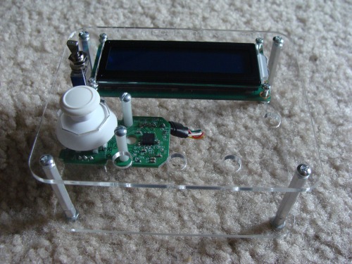
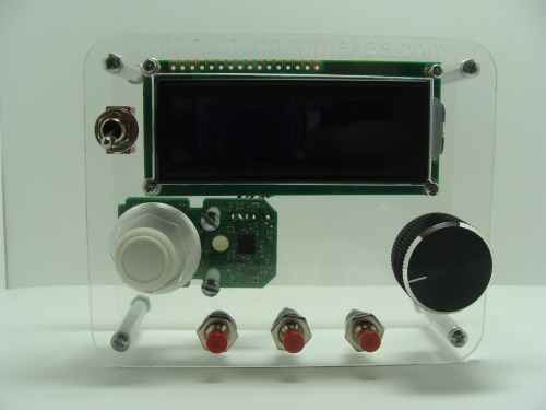
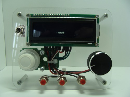
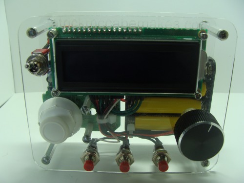
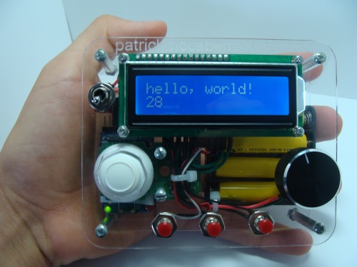
Here is my custom controller version 2. I made it so I can have some input to my robots and get information back.
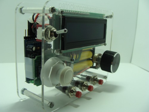
It is a simple design. It has a LCD, Xbee, custom LCD Arduino backpack, 3 button inputs, a potentiometer, and a wii nunchuck. The buttons will allow navigation through the menu system and sending simple commands within the menu. The wii nunchuck will allow for manual control of a robot by using either the joystick or tilting action with the accelerometer. The potentiometer will allow adjusting of variables like speed. The custom LCD backpack will minimize connections.
I will just go ahead and dive into the construction of it.
The acrylic plates were laser cut out.
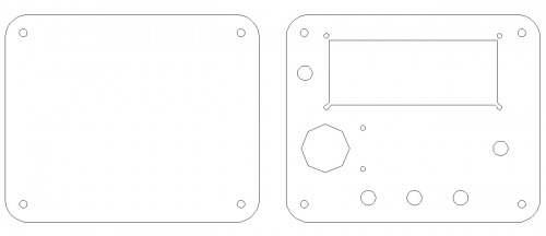
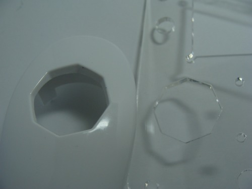
The joystick cutout is an octogon like that of the actual wii nunchuck.
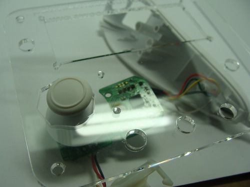
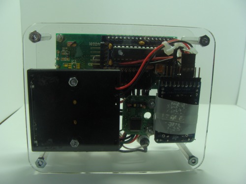
Next I bolted the LCD and power switch on. The wii nunchuck is attached using bolts and spacers. The 2 plates are connected together using some standoffs.
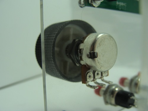
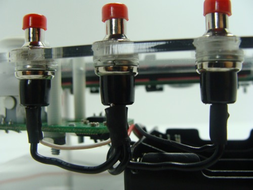
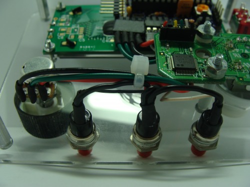
Then came bolting on the buttons and potentiometer. The potentiometer is then topped off with a shiny black knob.
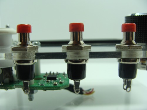
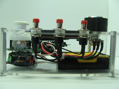
I then wired the buttons up. I distributed a ground wire and attached an output wire to each using a servo cable. They will be controlled using the internal pullups in the atmega. I also bolted the battery holder down. "But wait Patrick, there are no holes in your design for bolting the battery holder down." Yeah I know, I did not plan for it. I had to drill some to bolt the battery holder on. Oh and of course the bolts were too long so I cut them with my dremel.
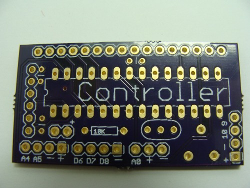
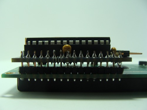
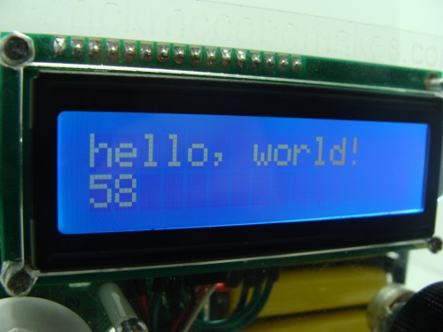
Here is my custom LCD backpack Arduino controller I made for this project. It has all the inputs I need and directly mates with the LCD.
I did not hesitate to solder the board together and attach it to the LCD. The 90 degree headers blocked the labeling on the silkscreen and I got the FTDI port switched around so the cable has to be plugged in upside (I always end up doing this). Despite those nit picks, I tested it at this point and it worked.
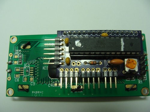
There are those black tabs on the back of the LCD that prevents it from being flush against the LCD. I knew about these and it does not hinder construction in any way.
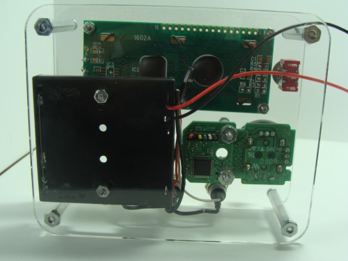
So next came the wiring and plugging of inputs into the LCD backpack.
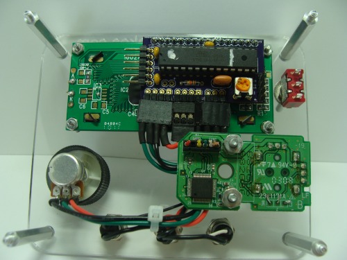
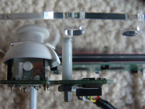
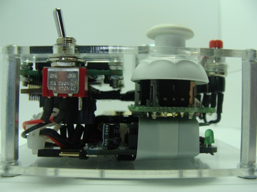
The second stage of wiring was the battery pack and Xbee. It was then done.
The white electrical tape around the Xbee prevents it from making electrical contact with the wii nunchuck above it.
Well that is all folks. Check out the video for a demo.
UPDATE 6.23.11
New video with RC demo.
https://www.youtube.com/watch?v=u5egHV2l_So
