Introduction:
Till today two humanoid robots have been entered space. The first one was the US-built robot Robonaut 2, delivered by STS-133 in February 2011 to the ISS (International Space Station). The second one was the Japan-built robot Kirobo, launched on the cargo-carrying rocket on August 2013 loaded with supplies for the crew of the International Space Station, along with a small robot meant as a companion for the Japanese astronaut Koichi Wakata.
While Robonaut 2 is quite dexterous and mostly tele operated but can't talk, Kirobo claims to be the first talking humanoid robot in space, but has much less degrees of freedom, comparable with a humanoid robot kit you can buy in corresponding shops. Cosma, as I named my robot, a maiden name, ancient Greek for Cosmos, could be the third humanoid robot entering space. This sounds like a day dream, but it's really feasible, especially because I might have access to an according carrying system - the eXSShot rocket, powered by sugar propellant, capable of breaking the Kármán line, defined as an altitude of 100 kilometres above the Earth's sea level, and commonly used to define the boundary between the Earth's atmosphere and outer space. The rocket is under development by the Sugar Shot to Space team, and it happens that I am a member of this team and also the main backer. The project is far away of being a success; we had many CATO's (Catastrophe At Take Off) in the past, and the rocket prototypes burning more money than fuel, but hey, at least I can do everything in my power making this an access some day.
Cosma is now not very dexterous. The current version has even no any kinematic degree of freedom. Cosma can talk well, but this isn't the point. The main goal of Cosma is to map its sensor data into physiological human conditions, something neither Robonaut 2 nor Kirobo can do. Once, physiological human conditions have been computed, simple mental human conditions can be derived.
The idea is to collect bio medical data of astronauts and flight data at a time t in a lookup table and compare the robot sensor data then with the lookup table data via min-max algorithm to find the best match.

Fig. 1 Abstract of RESULTS OF THE FIRST UNITED STATES MANNED ORBITAL SPACE FLIGHT. Blood pressure, body temperature, respiration and activity of the heart of astronaut John Glenn was measured during the flight. The sample showing physiological data at drogue parachute deployment.
Construction:
I started to build this robot by populating the Arduino shield PCB I had designed for the previous Cosma prototype, leaving the voltage regulator, capacitors for the servos and pin headers for the servos, sound sensors and FSRs out, as I didn't want to use this actuators and sensors to make the robot as light weighted as possible and trim it especially for a weather balloon test flight. FSRs and sound sensors making not much sense, if the robot is hanging on a weather balloon. This might change if the robot is pressed into its seat in a rocket capsule, surrounded by a deafening sound during takeoff.
Following the KISS principle, I have not added a voltage monitor circuitry for the LiMH battery. Just a shutdown timer is used.

Fig. 2
The EMIC-2 TTS module is the only device which I didn't integrate into the shield. It can be plugged in if needed. It is normally only needed if a live audio down link is available. If not, generated text respectively the physiological and mental condition of the humanoid robot will be stored on the SD card and can be later readout in case the robot returned safely back to Earth.
The EMIC-2 module doesn't work properly with hardware serial. The problem is the hardware RX on the Arduino. It never receives the char ':' flawlessly, which indicates that the EMIC-2 isn't busy anymore, so I revised the PCB accordingly and changed the communication protocol to software serial. On the other hand, having the LS Y201 TTL camera on software serial too, it was blocking the communication of the EMIC-2 module. Fortunately the linksprite camera works on hardware serial as well without problems, so I re-wired TX of the camera to RX1 and RX of the camera to TX1 on the Arduino board/shield. More information can be found on that topic, reading the snap shot example comments of the adafruit library. The camera's serial data pins are 3.3V logic, so a voltage divider must be used on the camera's RX pin when connected to a 5V level MCU.
Fig. 3
The MPU 6050 (6 DOF accelerometer/gyroscope) in its QFN package is on a GY-521 breakout board. I soldered the breakout board via right angle male headers onto the shield. In order to make the MPU 6050 breakout board working, I removed the weak 2.2 kΩ SDA and SCL pullup resistors (I am using a BSS138 N-channel MOSFET based voltage level shifter with 10 kΩ pullup resistors on the 3.3V level SDA/SCL side) as well as the 4.7 kΩ pulldown resistor on AD0 and connected the AD0 pin directly to 3.3 V to set the I2C address to 0x69 (AD0 logic HIGH) instead of 0x68 (AD0 logic LOW), which is the default address of the RTC (DS1307) and cannot be changed.
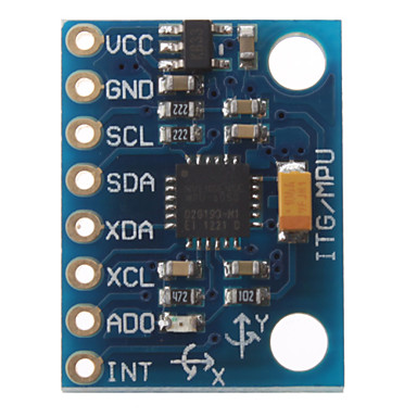
Fig. 4
To give the robot a little bit more personality and let it not looking completely static, I integrated a red LED into the mouth section, which flashes randomly during speech and gives a nice effect.
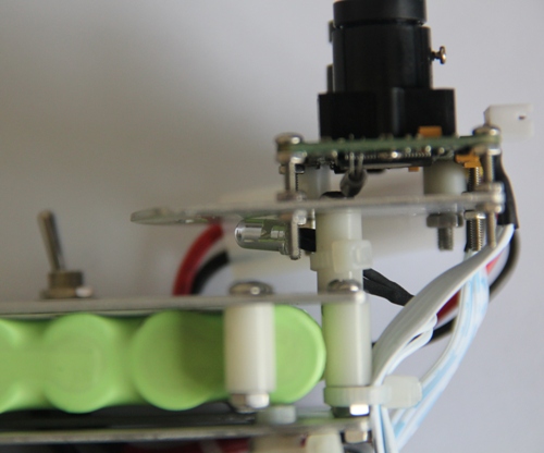
Fig. 5
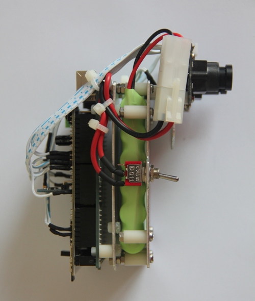
The mechanical construction is straightforward. I cut out three mounting plates from 1.5 mm aluminium sheet, one for the Arduino board, one for the battery and one for the cameras:
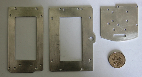
Fig. 6
I am using a special utility knife and a steel ruler as a guide to score the material and then just simply breaking the pieces off. To make the parts as light weighted as possible inner cut-outs were done by pre-drilling the pattern, removing the material and finishing it with a small flat file and sanding paper.
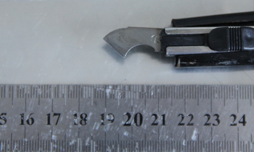
Fig. 7
The mounting plates were then bolted together, using nylon stand-offs.
Fig. 8
The complete robot including the battery weighs 311 g.
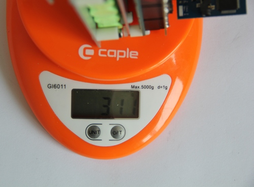
Fig. 9
To keep the robot warm and dry during its flight on the weather balloon, it will be simply packed into a plastic bag of according size with cut-outs for the camera and light sensor.
Updates:
[8/25/2013] I decided to layout a new shield with integrated camera, TCS3200 color sensor and SMD LED for the mouth. This avoids long wiring between the camera/TCS3200 color sensor and the shield and reduces the depth and the weight of the robot. On the new shield will be only SMD components used. The schematic can be found in the attachment.

Fig. 10
I furthermore designed a battery box on which the Arduino Mega is mounted.
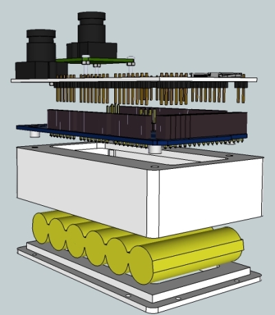
Fig. 11
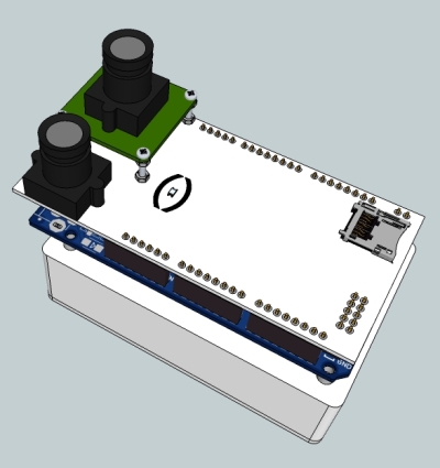
Fig. 12
[9/28/2013] New PCB populated and battery compartment 3-D printed. Robot assembled.
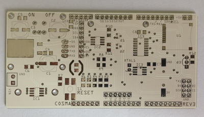
Fig. 13
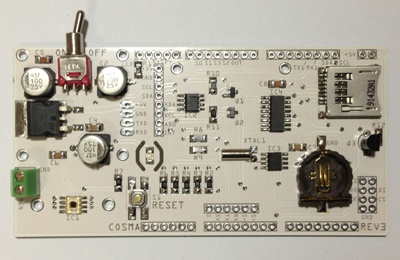
Fig. 14
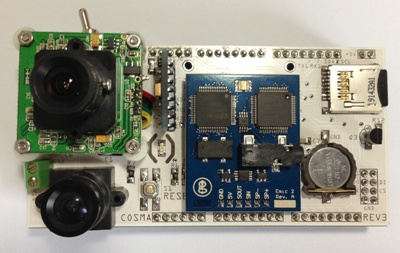
Fig. 15

Fig. 16
Fig. 17
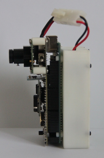
Fig. 18
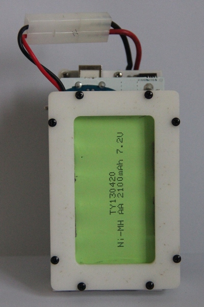
Fig. 19
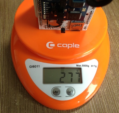
Fig. 20 The weight is reduced by 34 g
[10/1/2013] Data logging code for Cosma Mk IV written. The robot will be shipped next week to the US to encounter near space on a weather balloon.
[10/15/2013] After a lot of trouble with the Chinese customs and changing the express company a few times, COSMA finally reached US soil and will be launched on a weather balloon soon...
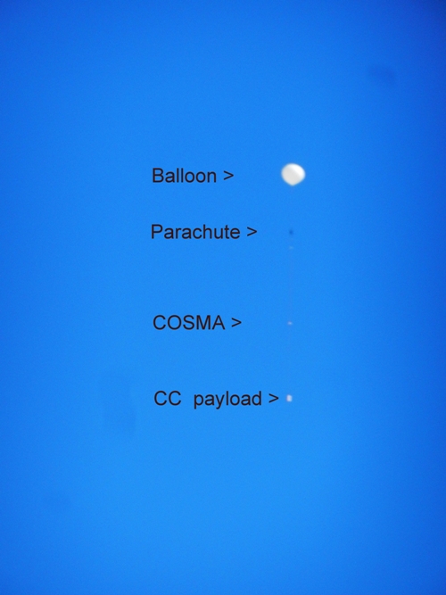
[2/10/2014] Cosma was launched this morning and reached over 30,000 meters! I just copy/paste the email my friend sent me today. More information will follow...
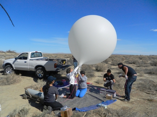
[17/2/2013] COSMA is back after a trip to 102,000' and 7 days on the side of a Mojave Desert Mountain. I will publish the data and photos shortly. It seems COSMA was switched on way to early prior launch, so all the robot did was data logging while sitting for hours on the ground and waiting for lift-off due to its pre-programmed timer interrupt.
Reports from space, maps sensor data into physiological and mental human conditions
- Actuators / output devices: LED, EMIC-2 TTS module
- Control method: autonomous
- CPU: Arduino Mega
- Power source: 7.2 V/2100 mAh LiMH battery
- Programming language: Arduino C
- Sensors / input devices: DS18B20, TCS3200, MPU6050, DS1307, linksprite JPG TTL camera
- Target environment: Space
This is a companion discussion topic for the original entry at https://community.robotshop.com/robots/show/cosma-mk-iv-reached-over-30-000-meters-and-recovered


