I have been following the instructions provided to create and build the robot, and I am currently at a stage in which I should be able to control the robot with the Lynxmotion PS2 Controller.
Currently, when the power switch is toggled on the robot sets to it’s basic configuration. The PS2 Wireless adaptor will show a solid green light with a blinking red light, while the controller itself will show a flashing red light on the left LED.
I tested the controller with a PS2 system and it worked with all lights on both controller and reciever solid.
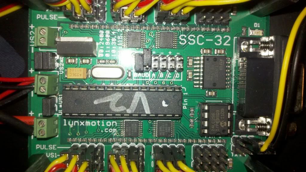
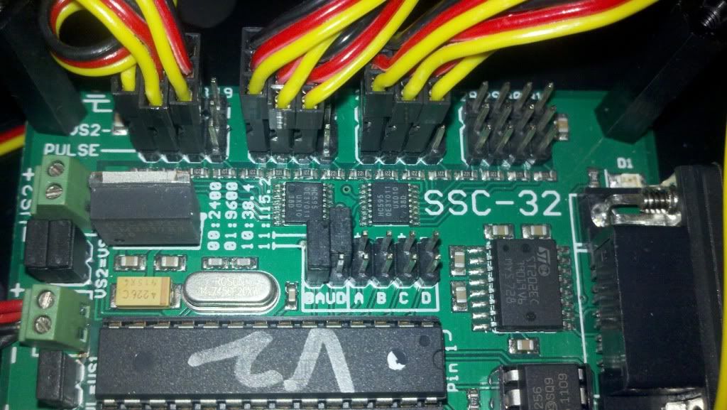
I have the jumpers on the SSC 32 board set to provide a baud of 38.4Kbps, and have connected the PS2 reciever as shown in your pictures. It currently has 2 wires that are not connected, with my only thoughts being that one of those wires needs 7.5Vdc. (not sure on this, as I cannot find conclusive evidence.)
I get a few short, consecutive beeps at start up, but from what I’ve read that’s normal.
Other than that I am lost as to what I should do. Any help would be appreciated.
Pictures provided below. If any more are needed, please let me know.
sounds perfect. we need to know what tutorial you have used so we can make sure your set up and baud rate is correct and also a photo of your SSC!
My thoughts are that you have a power problem with your servos.
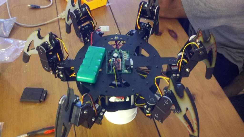
Oh and you need to peal off the plastic protective film on those lexan panels!
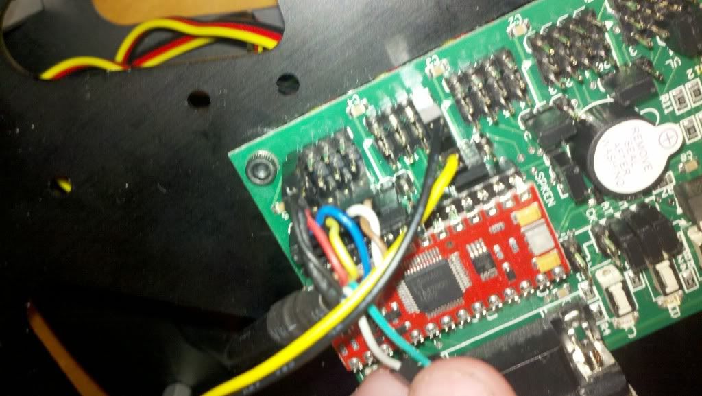
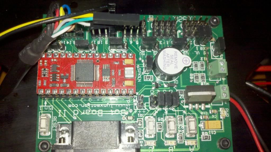
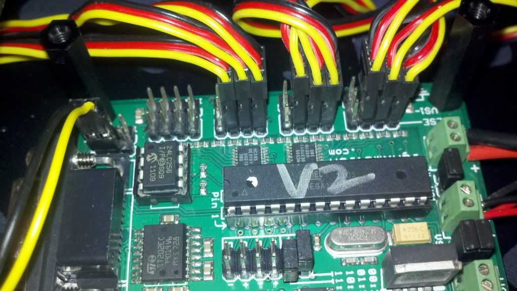
Would be better if we could see the power wiring as well. It is possible to plug the receiver into the cable upside down. I’m not confident the Atom chip is properly installed. I think it needs to be seated more into the socket.
We will get this working. More pictures, with entire board showing, SSC-32 and Bot Board II.
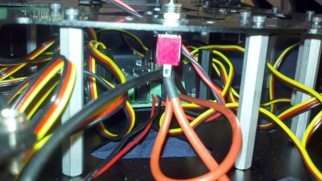
The last are is a little messy, so I tried to show you a picture of the connections themselves.
You’ll notice two pair of the thin gauge power wires. They connect to the 9v Battry clip, and to the VLogic input of the BBII.
The thicker wires connect to the switch, which connects to the main supply.
I am of the understanding that the 9v battery is just to supply the logic. As of the moment, I’ve just been powering the board with main battery, even during programming. I’ve tried it with all power sources connected with no difference.
I understand that the chip looks like it’s unseated, but I think it just has very long pins. Pin28 looks a little off especially, but it’s as firmly seated as the rest. I’ve pulled it out with a gripper and re-seated it twice, and this is the lowest it can get. I’ve pressed down between a bottom mat with a rubber press on top and I can’t get it to seat any further. Anything else and I’m worried about damaging components.
I hope this information helps. Thanks again!
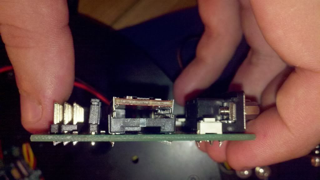
Edit: I just wanted to say that the wireless reciever seems to be seated correctly into the base which is installed to the BBII. I read other posts where people say it was installed upside down, but I’m not sure as how that’s possible without really forcing it. Kind of a square into round hole type of thing. Unless, I’ve got this mistaken for some other mistake, i just thought it would be good to note.
I think I see a pin on the left side (a few in) that is in too far towards the center of the socket. Any pins bent/wrinkled?
If you send something back, maybe send the BBII also, so that the chip can be properly seated.
I like to try a slight “rocking” motion, which with a little pressure will generally work the pins further in. However, the pins need to be straight; and properly aligned with the socket.
Yeah, looking at the picture makes it seem worse than how it looks.
If I need to ship this back with the controller, what’s the expected process/turn around?
The pin that looks too far in is slightly bent, and that was the best I could make it seat. Even the back side of the chip doesn’t want to seat any more than it has.
If the chip needs replacing, that’s not really an issue. Just let me know what to do.
Also, I hooked up a corded PS2 controller and the robot would stand, seem like it tried to move, then fall. I thought maybe the controller was too much an added drain to the battery.
Other than that, just let me know what to do and I can try to get it overnighted to you hopefully by tomorrow.
2a) If it does not work, what is the outputs shown on the screen. Is it valid data or all 0’s or 255s? If it is valid data, and still blinking, it says that receiver is at least working well enough to talk to the BAP, if it is all 0’s or 255s, than it is not talking.
2b) If it is not talking correctly, than need to double check things like:
a) Is the PS2 correctly installed into the PS2 cable. I think it is hard to do, but is it plugged in upside down…
b) Check how the wires are plugged into the BB2. On most of the cables, I believe that there is a brown wire on one side of a 4 pin connector. Is that plugged into the P12 on the BB2? Also is plugged into the IO pin (the ones closest to the center of the board). Is the power and ground pins connect properly. Is the power pins for that group of IO pins configured for +5v and not VS.
c) Sometimes it helps to remove the 3 jumpers/shunts above the speaker that connect to the three LEDS and buttons.
d) if the PS2 is not talking at all, check to see if the IO pins are working… Could run a simple program like:
i var byte
Main:
   for i = 12 to 15
       toggle i
       pause 100
    next
goto main
Warning this code was typed in on the fly so could have bugs…
If in this step you have the 3 jumpers installed that I mentioned in c) the three LEDs should go on and then off… This will show that you can talk to P12-P14. Won’t show P15. However if you have a Servo extension wire or other like jumpers you can remove these jumpers, and use the extension cable, by plugging it into 3 pins, like P13-P15 and plug the other end into the upper row on pins where you removed the shunts from(nearest the buttons). With the above code and if you did P13-P15 with the cable, you should be able to verify now if P15 works as well… Note: several of us use this trick of bumpering some IO pins to these pins to help debug code (or hardware).
There are probably lots of other tests you can do, but these should help to localize what to do next.
I appreciate the response and all the help you all have provided.
I’m going to be working on my robot this saturday, and I’m going to try all the things you have said.
I’m hesitant about the atom chip. Pin 28 is supposed to be Vin. If Pin28 wasn’t connected to the board via the seat, then would I even be able to program it? Basic Atom software says that it connects and that that the programming was complete.
Should I still have problems then I’m of the determination that it will likely be the chip. That being said, I do not think I can seat the atom chip without breaking pin 28, so I’m pondering soldering it directly to the board. That’ll be hard to do without overheating it, so I don’t usually like to soldier IC’s directly.
Last case scenario there. After that I guess the only thing i can do is send the entirety of the robot back to you to have a look. At that time I’ll pay for an additional ATOM chip/BBII so you know that everything is functional and seated properly.
I do appreciate all the help. I’ll keep you updated.
Before I start with my programming trials, I wanted to say that I used a DMM to perform a continuity test on the IC. I tested from each pin to it’s associated socket on the bottom side of the board. Everything checked OK.
So I followed the direcitions which the link provided. I wrote the code to the card, and programmed it declaring it as a BBII and version 8.0.1.7.
2a) What I saw matches Figure 2-1 in the tutorial. I still had the same status indicators as before; On the reciever a Solid Green (Left LED) and a flashing Red (Right LED). On the controller the left of the two LED’s was a flashing red, and the right most LED was off. I still could not establish a connection. When I moved the analog’s or pressed any digital keys I had no response from the program, and my numbers remained the same.
I also tried the program you wrote in 2d, and my BBII LED’s would flash on/off in a sequential order. Looking at the code that seems what it’s supposed to do.
From what it seems based on what you’ve said and I’ve seen; the PS2 reciever is talking to the robot, but I just cant get the controller to sync with the receiver.
So any ideas from there? Should I mail you the robot and controller? If so what’s that general procedure, and is it listed on your site?
So we now know the processor is working. Note on 2: I would recommend using the most recent versions of Basic Micro Studio(forums.basicmicro.net/). Nathan normally announces new releases in the News section. I often will also post it up on this forum, but I have not mentioned the last two builds as they are NANO specific.
I assume you have tried replacing the batteries in the remote. Also when the program starts up, try turning the power off on the remote and then back on. Try that a couple of times.
I can help you if it’s time to get the PS2 tested in house. Please don’t send the entire robot, only the PS2 controller/receiver and Botboard with Atom Pro. Let me know and I will PM you with details.
That is the verson of Basic Micro Studio that I’ve been using. I haven’t edited the base program. The only programs I have tried to use are the ones generated by PowerPro.
The batteries in the remote are right out of the package. I tried swapping it on and off a few times as well as attempting to toggle the analog setting.
If you could PM me and let me know what to do to send the materials back that would be awesome.
I had to go out of town for the week on business so I gave the robot over to a friend who has been working on it with me. There is the possibility that they’ve mailed you the entire robot… I’m not sure of the address they may have found, but if they found one then it was off of your website most likely.
If you can let me know via PM that would be great. I’ll let you know what we did when I find out myself.
We’ve got your board in for testing. Looks like your VS=VL trace was fried! Granted, this didn’t cause any problems with your setup, but it does make me wonder how that happened. Turns out that there was a bad PS2 receiver in the mix. We’re going to go ahead and replace that. Hold for Jim for more words regarding this.


