I got a 18X starter pack because i wanted to learn the picaxe philosophy before actually building my first robot, but i'm almost starting to regret it as it's kind of hard to find informations, compared with the 28X1 which has plenty of documentation (here on LMR, or even in the manuals, which always refers to the 28X1 project board). Anyway i'm sure i still can do a lot with it, but i think i need some help...
How many analogue inputs does the board have? I'm sure everybody is going to scream "RTFM!!!", which would be a normal answer, but the thing is, you can find 2 different answers according to which manual you're looking at! In the board datasheet (http://www.rev-ed.co.uk/docs/CHI030.pdf , page 4), it says that there are 2 analogue inputs, input 0 and input 1, and in the picaxe manual 1 (http://www.rev-ed.co.uk/docs/picaxe_manual1.pdf , page 8) it says 3...
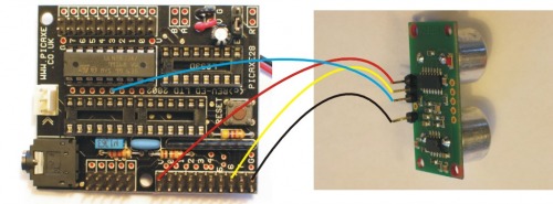
Now question about the SRF05 ultrasonic rangefinder... it looks like it's a bit tricky to connect, even with the manual, as Fritsl had to write something about it... he made that great diagram :
which is very clear, so does anybody have experience with the 18x and the srf05, is it mysterious as well? If so, can you show me how to connect it?
I must add that i don’t have one yet, but i plan to get one, and i don’t want to if i’m not sure i’ll be able to use it…
Another question, that may sounds stupid for you, how do you connect a servo? Once again, "RTFM, but i’m really confused about what i read. I know i need a 330Ohm resistor, as explained in the StartHere tutorial, but i’m not sure where i’m supposed to put it. Looks like i have to get rid of the Darlington? But without the Darlington, will i be able to control other things like a led, or a dc motor? Again, if someone could simply draw the connection, it’d be great!
Finally, last little question, i have a mini piezo transducer, but when i connect it like explained in the manual, the sound is very very very weak… i have to put my ear really close to hear something, and it’s just a little sound. I (just) noticed that the website says “Requires an external drive circuit”, but i have no idea what it means…
Well, that’s it, thanks for reading, thanks for your future answers, and thanks for helping a very motivated noob!
a) try fixing the buzzer firmly to a larger object. The larger object will resonate with the piezo and amplify the sound
b) search LMR for "SpeakJet". I made a post about amplifying the output from a SpeakJet chip (which is effectively the same as what you want to do), and someone else posted one before me.
The simple answer is nothing will plug-right-in. Nor will you be able to solder any “pins” to the board to use it like the 28x board. All is not lost, though. You are simply going to have to make some connections and add some components off the board. You can use a breadboard for this or get a simple blank PCB from radio shack and start soldering. First off, pull up the data sheet for the 18x board from picaxe and familiarize yourself with what each connection does. Each one is an input, an ADC input, an output or and output from the darlington. From there, you just have to match things up.
The SRF05 -You are going to need to find a +,-, one input, and one output. Now in terms of the output, things are a little funny.
Get rid of the darlington and in it’s place you will add a 330R resistor where you would want a servo (this is shown in the start-here robot) you will need to put a little jumper wire where you want a regular output. Now you can mount your darlington on a external board if you want to run motors etc. --Note, even on the 28x board, you can’t run servos and a darlington at the same time.
Believe me, i’ve read the 18x datasheet a loOot of times! I’m starting to get how it works, and have made some experiments. But I didn’t notice there were different types of outputs, direct outputs and outputs from the darlington.
About the SRF05, i think i understood how i’m supposed to connect it, but it’s the Fritsl’s walkthrough that actually scared me.
"Note, even on the 28x board, you can’t run servos and a darlington at the same time."
Ok that’s an important thing i didn’t know. So i saw in the starthere tutorial how i have to put the 330R resistor, but i don’t really understand this : “you will need to put a little jumper wire where you want a regular output.” If i understand well, the darlington is useless? (actually, i’m sure it isn’t, but i don’t really get what it’s for). Anyway, i mostly want to control servo or continuous servo so that’s ok, and if i’m not wrong, i think i can at least connect small components like a LED.
Thanks for everything, i think i’m just realizing how many things i still have to learn!
The bottom line is the picaxe can only send out a tiny tiny signal. The Darlington is a little “amplifier”. Thats it really.
You are right, it looks like all the 18 outputs goto the darlington. The 'jumper wire" will sorta “jump over” where the darlington used to be. It will connect straight across from one side of the darlington’s socket to the other. This will “reconnect” the picaxe to the connections on the right side of the board.
"The bottom line is the picaxe can only send out a tiny tiny signal. The Darlington is a little “amplifier”. Thats it really."
Cool, finally i really understand what is it!
“You are right, it looks like all the 18 outputs goto the darlington. The 'jumper wire” will sorta “jump over” where the darlington used to be. It will connect straight across from one side of the darlington’s socket to the other. This will “reconnect” the picaxe to the connections on the right side of the board."
Ok i get it. I think i’ll put eight 330R resistors, so i’ll be able to directly connect servos or LED.