Compact - an Arduino SHR

I wanted to make a small Arduino robot using an original Duemilanove and the Robot Builder's Shield. But I also wanted to have a chassis plate so I can mount the parts on. I started to play with the parts to see how they will fit together and finally came up with this design that looked so compact that it became the name of the robot. After a little AutoCAD drawing, some CamBam fiddling and nerve braking CNC-ing, there is the first imperfect chassis plate:

I also made a different one, but I'll show it later.

I threaded the holes with a #4-40 tap (that was the only one I had, I'll have to find a M3 tap). Then I started to mount the motors, battery holders, the ball caster, the Arduino board and the servo. Then I had to take off the Arduino board because I needed to add a bigger hole to pass the motor wires through. I installed the shield on top and soldered a switch to the solid wire I used to route the power from the power connector on the shield to the Vin pin so the Arduino board will get the power from there. Since I am using 6V, the resulted regulated voltage is 4.88V. Unfortunately I can't change the SMD voltage regulator with a LDO version onboard the Arduino, too small to solder by hand and of course, I don't have a proper SMD regulator. But I think it'll work fine.

Here are more pictures of the robot, a video will follow soon:


Arduino Start Here Robot

  • Actuators / output devices: 2 x 1:100 Pololu micro motors
  • Control method: autonomous
  • CPU: Arduino Duemilanove 328
  • Power source: 6V, 4 AAA Cells
  • Programming language: C/C++
  • Sensors / input devices: Sharp IR
  • Target environment: indoor

This is a companion discussion topic for the original entry at https://community.robotshop.com/robots/show/compact-an-arduino-shr

Hey, glad to see you

Hey, glad to see you demonstrating your shield! Nice work and a good clean build. I can’t wait to see it working.

Will you post your code as well?

Beautiful & elegant!

I like your design. it´s compact and yet has plenty of room for expansion!

By using 4 AAA rechargeable batteries you can have a single (almost) 5v power source.

Thanks,Of course, but not

Thanks,

Of course, but not tonight, I still have some tweaks to do. But as soon as I have it done and a video shot, I will post both.

very nice

Although I love the humble PICAXE SHR it would be nice to push one of the “big boy” micros as an option for the newbies. Who knows, maybe I would have gotten a “Doo-ehhhm-eeee-luhhh-noooo-vayyy” (say it slow, try to get it right son…) instead of the 28X2. Great Amiga, I’m glad the new one is a just "Uno."

Collected!

Thanks,Yes, 4 rechargeables

Thanks,

Yes, 4 rechargeables can be plugged directly to the microcontroller, bypassing the voltage regulator, but they need a bigger capacitor to keep the voltage steady when the motors start or stall (you should always design your robots with extra power so the motors never stall but the wheels slip). However, in that case I would rather go for a 3.3V regulator for the electronics, that means a different board than Arduino. The uBotino works with 3.3V regulator, all you need to do is replace the 16MHz resonator with an 8MHz one (and change the fuses, the bootloader…).

Looks great --Why is mine not working?

I can’t believe I am asking this question. I have followed all the traces on the board, etc.

I gotta be missing an enable or something but I am sending LOW to all 4 pins and my motors are still going.

int motorpinA=4;
int motorpinB=7;
int motorspeedA=5;
int motorspeedB=6;


void setup(){
  pinMode(motorpinA, OUTPUT);
  pinMode(motorpinB, OUTPUT);
  pinMode(motorspeedA, OUTPUT); //this should be PWM later
  pinMode(motorspeedB, OUTPUT); 
}

void loop(){
  digitalWrite (motorpinA,LOW);
  digitalWrite (motorspeedA,LOW); //this should be PWM later
  digitalWrite (motorpinB,LOW);
  digitalWrite (motorspeedB,LOW); //this should be PWM later
}

What the hell am I missing, I feel like a total tool, here.


Did you make the

Did you make the modification, that Ro-Bot-X made on the Arduino shield? There was a short cut on the first board revision.

Code:

<code>

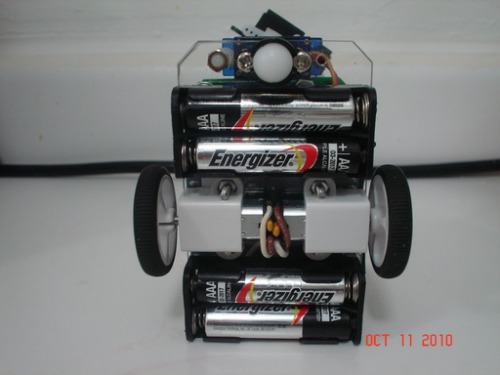
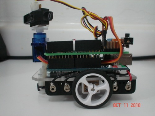
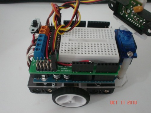
// Compact, a small Arduino (Duemilanove) robot
// 2 Pololu micro motors 100:1 and small wheels,
// one HXT900 micro servo, one Sharp IR sensor,
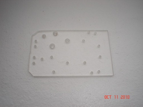
// 2 AAA battery holders, the Robot Builder’s Shield
//
// Arduino pinout:
//
// Shield  Funct Arduino  ATmega168      Arduino Funct Shield
//                       ±----/----+
//          Reset       1| PC6   PC5 |28  D19 A5  SCL  
//          Rx    D0    2| PD0   PC4 |27  D18 A4  SDA  
//          Tx    D1    3| PD1   PC3 |26  D17 A3        
//          Int0  D2    4| PD2   PC2 |25  D16 A2        
//          Int1  D3    5| PD3   PC1 |24  D15 A1        
//      M1B       D4    6| PD4   PC0 |23  D14 A0        IR sensor
//                      7| VCC   GND |22  
//                      8| GND  AREF |21  
//          Xtal        9| PB6  AVCC |20  
//          Xtal       10| PB7   PB5 |19  D13      SCK  LED      
//      M1A OC0B  D5   11| PD5   PB4 |18  D12      MISO Pan servo
//      M2A OC0A  D6   12| PD6   PB3 |17  D11 OC2A MOSI       
//      M2B       D7   13| PD7   PB2 |16  D10 OC1B      
//                D8   14| PB0   PB1 |15  D 9 OC1A      
//                       ±----------+
//

#include <Servo.h>

//Inputs/outputs
#define Motor_1_PWM   5 // digital pin 5    // Right Motor
#define Motor_1_Dir   4 // digital pin 4
#define Motor_2_PWM   6 // digital pin 6   // Left Motor
#define Motor_2_Dir   7 // digital pin 7

#define IR_Pin  14 // digital pin 14 (analog pin 0)
#define PanPin  12
#define LedPin  13

#define SR 1 //Sharp Short Range sensor
#define MR 2 //Sharp Medium Range sensor
#define LR 3 //Sharp Long Range sensor

#define center 90

//Variables
byte dir=0;
byte speed1=250;
byte speed2=255;
int turn90=110;
int turn45=55;
int straight=500;
int stopTime=200;
int IRdistance=0;
int treshold=20; //20cm min distance

Servo Pan; 

//-----------------------------------------------------------------------------

void setup() { 
  // set motor pins as output and LOW so the motors are breaked
  pinMode(Motor_1_PWM, OUTPUT);
  pinMode(Motor_1_Dir, OUTPUT);
  pinMode(Motor_2_PWM, OUTPUT);
  pinMode(Motor_2_Dir, OUTPUT);
  Stop();

  Pan.attach(PanPin);
  Pan.write(center); //90
  StepDelay();

  pinMode(LedPin, OUTPUT);      
  digitalWrite(LedPin, LOW);  

  Serial.begin (19200);
  Serial.println(“start”);

  Forward();

void loop(){
  Drive();
  //square(); //use this function to adjust the timings for turns
                 //and to make sure the robot is driving in straight lines
}

void square(){
  Forward();
  delay(straight);
  Stop();
  delay(stopTime);
  Right();
  delay(turn90);
  Stop();
  delay(stopTime);
  Forward();
  delay(straight);
  Stop();
  delay(stopTime);
  Right();
  delay(turn90);
  Stop();
  delay(stopTime);
  Forward();
  delay(straight);
  Stop();
  delay(stopTime);
  Right();
  delay(turn90);
  Stop();
  delay(stopTime);
  Forward();
  delay(straight);
  Stop();
  delay(stopTime);
  Right();
  delay(turn90);
  Stop();
  delay(stopTime);
}

//--------------------------

void Drive(){
  IRdistance=Read_Sharp_Sensor(MR, IR_Pin);
  Serial.print("IRdistance ");
  Serial.println(IRdistance);
  if (IRdistance<10){
    Stop();
    StepDelay();
    TurnAround();
  }
  if (IRdistance<treshold){
    Stop();
    StepDelay();
    Avoid();
    Forward();
  }
  delay(50);
}

void TurnAround(){
    Reverse();
    Pan.write(center);
    StepDelay();
    Stop();
    Left();
    delay(turn90);
    delay(turn90);
    Stop();
    StepDelay();
    Forward();
}

void Avoid(){
  int prev=0;
  dir=2;
  for (byte i=0; i<5; i++){
    Pan.write(i45);
    StepDelay();
    StepDelay();
    IRdistance=Read_Sharp_Sensor(MR, IR_Pin);
    if (IRdistance>prev){
      dir=i;
      prev=IRdistance;
    }
  }
  Pan.write(center);
  StepDelay();
  switch (dir){
    case 0:
      Right();
      delay(turn90);
      Stop();
      StepDelay();
      break;
    case 1:
      Right();
      delay(turn90); //turn45
      Stop();
      StepDelay();
      break;
    case 2:
      Forward();
      break;
    case 3:
      Left();
      delay(turn90); //turn45
      Stop();
      StepDelay();
      break;
    case 4:
      Left();
      delay(turn90);
      Stop();
      StepDelay();
      break;
  }
  delay(500);
}  

// Read Sensors

int Read_Sharp_Sensor(byte model, byte pin) {
  int value = 0;
  value = analogRead(pin);
  switch (model) {
    case SR: //short range, aka GP2D120 (4-30cm)
      return (2914/(value+5))-1; 
      break;
    case MR: //medium range, aka GP2D12 (10-80cm)
      return 51384.4pow(value,-.9988); //I had to multiply by 5, different sensor
      break;
    case LR: //long range, aka GP2Y0A02YK (20-150cm)
      return 11441
pow(value,-.9792); 
      break;
  }
}

void StepDelay() {
    for (byte t=0; t<10; t++){
      delay(20);
    }
}

//++++++++++++++++++++++++++++++++++++++++++++++++++++++++++++++++++++++++++++++++

void Forward(){
  digitalWrite(Motor_1_Dir, LOW); // forward
  digitalWrite(Motor_2_Dir, LOW); // forward
  analogWrite(Motor_1_PWM, speed1); // 
  analogWrite(Motor_2_PWM, speed2); //
  return;
}

void Reverse(){
  digitalWrite(Motor_1_Dir, HIGH); // reverse
  digitalWrite(Motor_2_Dir, HIGH); // reverse
  analogWrite(Motor_1_PWM, 255-speed1); // 
  analogWrite(Motor_2_PWM, 255-speed2); //
  return;
}

void Right(){
  digitalWrite(Motor_1_Dir, HIGH); // reverse
  digitalWrite(Motor_2_Dir, LOW); // forward
  analogWrite(Motor_1_PWM, 255-speed1); // 
  analogWrite(Motor_2_PWM, speed2); //
  return;
}

void Left(){
  digitalWrite(Motor_1_Dir, LOW); // forward
  digitalWrite(Motor_2_Dir, HIGH); // reverse
  analogWrite(Motor_1_PWM, speed1); // 
  analogWrite(Motor_2_PWM, 255-speed2); //
  return;
}

void Stop()
{
  digitalWrite(Motor_1_PWM, LOW);
  digitalWrite(Motor_1_Dir, LOW);
  digitalWrite(Motor_2_PWM, LOW);
  digitalWrite(Motor_2_Dir, LOW);
  return;
} </code>

stupid question - doesn’t the L293D req 3 pins to drive 1 motor?

Hi,

New to LMR, amazing site!

I am also building an Arduino start here robot. I am waiting for my parts to arrive from SolarBotics, I wish I had known about your robot shield before I ordered the solarbotics Freeduino SB-Protoshield. (oh well, still would like one, pls let me know how to order).

I am really confused about using the L293D. My understanding is that it takes 3 pins to drive each motor - 2 inputs and enable. You can adjust the speed by using PWM on the enable pin. Is that correct? Do you have the enable pin tied to 5V or something? So that it always goes full speed, and you only need 2 pins per motor?

It would be great if there was a link to this page from the start here page, b/c I spent a lot of time trying to figure out how to convert the picaxe Start Here to the Arduino, before I found your page.

Thanks, dg


Hi DG,I use an alternative

Hi DG,

I use an alternative method of Sign Magnitude control. The Enable is hardwired High and I use the direction pins to drive the motors. One of these pins is tied to a PWM output and the other to a regular output pin. This pin becames the Direction pin and the other the PWM pin. When the Dir pin is Low, the duration of the High period of the PWM signal will determine the speed of the motor. For instance, a 255 PWM value will result in full speed and 0 will brake the motor. When the Dir pin is set High, the duration of the Low period of the PWM signal will determine the speed. A 0 value will result in full speed and a 255 value will brake the motors. So to set the speed for Reverse you need an inverted PWM signal. To get a regular PWM signal inverted, I subtract the PWM signal from 255. Why 0…255 values instead of an integer? Because the Timer0 is an 8 bit timer, so using an int is a waste of memory space.

very cool

Thanks for the great explanation, I think I got it the 4th time I read it. For me just starting out, I have all my pins available and tons of memory. I was planning on using all 3 pins for each motor. Is there any disadvantage to doing it the way you have described? Why don’t they just make the chip without the enable?

I also saw some people have used an inverter chip to feed one of the direction pins, so they use enable and one dir pin. (again, why don’t they build that into the chip?)

Of the three methods, do you use this one because it uses the least resources?

Here’s one last stupid question:

My understanding of the chip is that you get dynamic breaking when you have all three pins, (Enable and both direction pins) High. So, with Enable always High, does the PWM signal (inadvertently) trigger dynamic breaking during the off part of the cycle? Does this have ill effects?

Thanks for your help!

dg

Besides the regular control

Besides the regular control method for the motors that uses 3 control pins, there are 3 other method of control that use less pins.

1. Use an inverter on the Dir pins and connect that to one pin of the microcontroller, then PWM the Enable pin. To achieve breaking, you need to tristate the Direction pin. I wanted to use this method, but needs additional parts and space was scarce, unless I was going to use SMD.

2. My method of control, that uses 2 pins from the microcontroller, hardwire the Enable High and PWN one Direction pin while the second Direction pin sets the actual direction. This method breaks the motors during the Off time of the PWM signal, but because of the internal construction of the H-bridge, it allows the generated current to go back to the batteries through the flyback diodes if the generated voltage is greater than Vbattery + diode Vdrop.

3. The Locked Antiphase control method, that uses only one pin from the microcontroller. This method is a mixture between the above 2 methods and has the Enable hardwired to High and uses an inverter on the Direction pins, that are PWMed. The motors will go backwards (full speed) for a PWM value of 0, stop for a PWM value of 127 and go forward for a PWM value of 255 (full speed). This method is also re-generative and it is supposed to be the best choice for a balancing robot. The downside of this method is that the motors use power when they are braked.

More info you can read here:

http://www.barello.net/Papers/Motion_Control/index.htm

StepDelay?

Ro-Bot-X,

Thanks so much for your great commented code, it has been invaluable as I try to button up my LMR Start Here Arduino robot. I am going to be a great example of why people would want the robot builders shield, I have wires everywhere.

re:

void StepDelay() {
    for (byte t=0; t<10; t++){
      delay(20);
    }
}

Why not just delay(200);? Were you planning on implementing a wait that is tied to the angle of rotation you are waiting for?

Thanks!

dg

That code is a reminiscence

That code is a reminiscence from the time I used the SoftwareServo library. The servos needed a refresh command issued every 20-40 miliseconds. The actual code was like this:

void StepDelay() {
    for (byte t=0; t<10; t++){
       SoftwareServo::refresh();
       delay(20);
    }
}

You can replace it with a regular delay(200). Actually test how long it will take for your servo to get from center (90) to 0 or 180 degrees and delay that amount.

thats a pretty neat robot I

thats a pretty neat robot I seriously mean it…that is all other robots I have seen or the one I have made have so many wires sticking out making it look like it needs a barber…

anyway I have seen a problem with many similar robots they often dont travel in a perfectly straight line … they always curve towards one direction…quite annoying…played with the coding but tat did not work…i guess its because 1 motor is slightly faster than the other…anyway 2 fix it??

btw congratz again :smiley:


This is a typical problem.

This is a typical problem. Search this site and you’ll see it mentioned. I have had the same issue. The motors are not 100% identical, so they may run a little off.  Answers I have seen posted included:

  • Live with it, who needs a robot that can drive straight anyway?
  • Take apart the motors, inspect all gears and shave/file any rough manufacturing defects, and grease gears
  • Small DC motors run faster in one direction than the other; try reversing the wiring of the slow motor (can’t with the GM9, since it is a right angle gear motor)
  • Use Pulse Width Modulation (PWM) to compensate (Probably a good solution.)
  • Use encoder wheels to monitor the relative speeds and compensate in software (with PWM or other technique)
  • Buy/make a differential gearbox

In my case the motors were just a little off at first, but later they were very off, and the bot kept turning right instead of going forward.  It turned out I had a faulty connection on one motor.  So if they are WAAAY off, you might check that you have firm connections to each motor contact.  If they are just a little off, that is a normal problem in robotics.

Great work!

Looks great is the most compact Arduino beginners robot on LMR I’ve ever seen! Neat plexiglass design. Your robot moves like if it has a rocketbooster in the video! After it has turned it slow starts and then suddenly boosts to max speed!

If you take a good look at

If you take a good look at the code, you will see that there are 2 variables called speed1 and speed2. Speed2 is at the max value (255), but speed1 is at 250, because that motor is faster than the other one and I tested out how much should I slow it down for the robot to drive in a straight line. But, this depends on the battery voltage level, you may want to make a voltage sensor and find the proper compensating factor depending on the read voltage. No encoders needed.

Wow thats one cute robot =)

Wow thats one cute robot =) How long can it go with 4xAA batteries?